You are using an out of date browser. It may not display this or other websites correctly.
You should upgrade or use an alternative browser.
You should upgrade or use an alternative browser.
What’s on *YOUR* workbench?
- Thread starter Bricksnbeatles
- Start date

Oh I remember doing that with a set of surface mount j201 - that was almost the end of me ever looking at electrical components or pedals againTesting a batch of J201s with the setups @temol posted recently.
This is kind of a pain, but those DCA75s don’t come cheap.
View attachment 66386
cliffs_trip
Well-known member
I've done the exact same thing, except I added the components too. Had to figure out how to wire it up that wayWhen I'm fabricating anything I always stick a piece of paper tape and use a sharpie to denote orientation. I once put 58 turrets at 12 cents each in backwards. I had to pull them all back out and do over. At least I found out that they are VERY hard to pull out. So, kinda good from that standpoint. But 7 buck$ down the drain....

Yesterday was my first try at breadboarding... did not went too bad, but not too well either. Looked like this at the end and did not power up...

I have no picture, but I discovered I need to connect the 2 sections of ground and power rail. It then powered, but I lost audio before the second transistor. So I began cleaning it. Found one or two wrong connections. Also read @BuddytheReow thread later and found I should not have forced my pots in the breadboard. Ooops, damages confirmed.

It now powers and works fine. Time to populate the pcb and box it.
Oh, it's a green russian muff.

I have no picture, but I discovered I need to connect the 2 sections of ground and power rail. It then powered, but I lost audio before the second transistor. So I began cleaning it. Found one or two wrong connections. Also read @BuddytheReow thread later and found I should not have forced my pots in the breadboard. Ooops, damages confirmed.

It now powers and works fine. Time to populate the pcb and box it.

Oh, it's a green russian muff.
Last edited:
UtilityBeltFX
Well-known member

It's alive!!! Test wiring only, waiting for higher quality jacks, but wow what a relief.
PunchySunshine
Well-known member

Erik S
Well-known member
3X10? That's neat!
PunchySunshine
Well-known member
3x10 @ 16 ohms each too. I thought that was odd too.3X10? That's neat!
Actually, no cab...yet. I plan to make it into a head like the 50-H and then make a cab for the 2x12 Utahs my buddy has for me for it. I picked up the missing OT on Reverb and now I just need to check for cold joints, get a verb tank and a set of tubes for it.

cdwillis
Well-known member
Starting on this Jawbreaker Big Muff. The enclosures are supposed to show up tomorrow.
View attachment 66550
Is that OSH Park's After Dark pcb service? I love how you can see the copper of the traces.
KR Sound
Well-known member
Sure is. I put the ground plane on the backside.Is that OSH Park's After Dark pcb service? I love how you can see the copper of the traces.

temol
Well-known member
Something like this happened...
Fits a standard 4-hole template. I'm just not sure whether the long boards won't collide with the 3pdt. Upper surface with slight slope.
Anyone interested? Only 1 piece available. I did it for practice")
Color to be agreed.
Maybe someone on this side of the pond? EU?

Fits a standard 4-hole template. I'm just not sure whether the long boards won't collide with the 3pdt. Upper surface with slight slope.
Anyone interested? Only 1 piece available. I did it for practice
Color to be agreed.
Maybe someone on this side of the pond? EU?


steviejr92
Authorized Vendor
A little redemption after the last screw up I made.
Here’s the new 125B style enclosure updated to have the brackets/tabs incorporated into the body. No more having the fabricate brackets!!
Here’s the new 125B style enclosure updated to have the brackets/tabs incorporated into the body. No more having the fabricate brackets!!


steviejr92
Authorized Vendor
Thats gorgeous!!Something like this happened...
Fits a standard 4-hole template. I'm just not sure whether the long boards won't collide with the 3pdt. Upper surface with slight slope.
Anyone interested? Only 1 piece available. I did it for practice
Color to be agreed.
Maybe someone on this side of the pond? EU?
View attachment 66563View attachment 66564

temol
Well-known member
Here’s the new 125B style enclosure updated to have the brackets/tabs incorporated into the body. No more having the fabricate brackets!!
Side tabs are great, I've used them sometimes. But cutting this outline by hand... For convenience's sake, I try to design straight cuts.
Have you checked whether the 8mm DC socket covers the chamfer of the hole? I try to deburr the outer edge of the DC socket hole as little as possible.
steviejr92
Authorized Vendor
Yeah I made sure! I know exactly what you’re talking about and they don’t sink into the chamfer.
These stencils were cut out using the little CNC I have. I wouldn’t dare attempt this by hand with the tools I have.
These stencils were cut out using the little CNC I have. I wouldn’t dare attempt this by hand with the tools I have.
JTEX
Well-known member
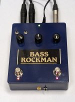
I gave up trying to feed my pedalized Bass Rockman from a standard 9V supply and generate the -6V rail internally. Nothing I tried was quiet enough, without any little whines or interference due to unavoidable close proximity to the sensitive main boards. Back to what the thing actually likes: a linear, regulated +/-6VDC supply. But which 3-pin DC connector to use? There was no way I was going for a 3.5mm stereo jack for power, like the original box. I think that's an aberration. I ended up using a TinyXLR, which I highly recommend for those times when you need dual rail power into the box. It's pretty much bombproof, very reliable contacts, won't accidentally unplug itself, and won't be mistaken for any other DC or AC power supply (or headphone jack!).


Last edited:
steviejr92
Authorized Vendor
So I think this might be an official color way from now on! 
I haven’t tried putting the stainless steel bolts on this color way but I feel like they would look good with this color combo…
I haven’t tried putting the stainless steel bolts on this color way but I feel like they would look good with this color combo…

