RetiredUnit1
Well-known member
Just be aware that running your bias too low can damage tubes just as much as running them too hot. Although you won't melt glass, lol. 70% is used for maximum life span.Imma reply to myself
I fixed my Deliverance. After two hours of probing, validating DC voltages, resistances and continuity, I decided to simply check AC voltages with a signal. Turns out, the amps works with not issues! I must have had a lose connection somewhere, or something when the amp is really hot? I cannot reproduce it though. So I re-secured all the Faston connectors and it works fine. I redid the bias to make sure, and lowered it a bit while playing. Turns out I really like it at 55%. Much less harsh while still remaining gritty. So there is that.

Did you ever get the oscillation fixed?
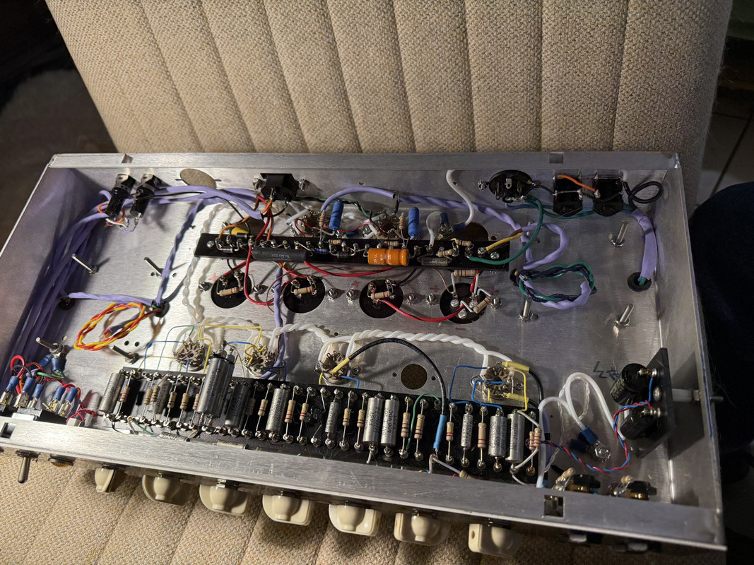
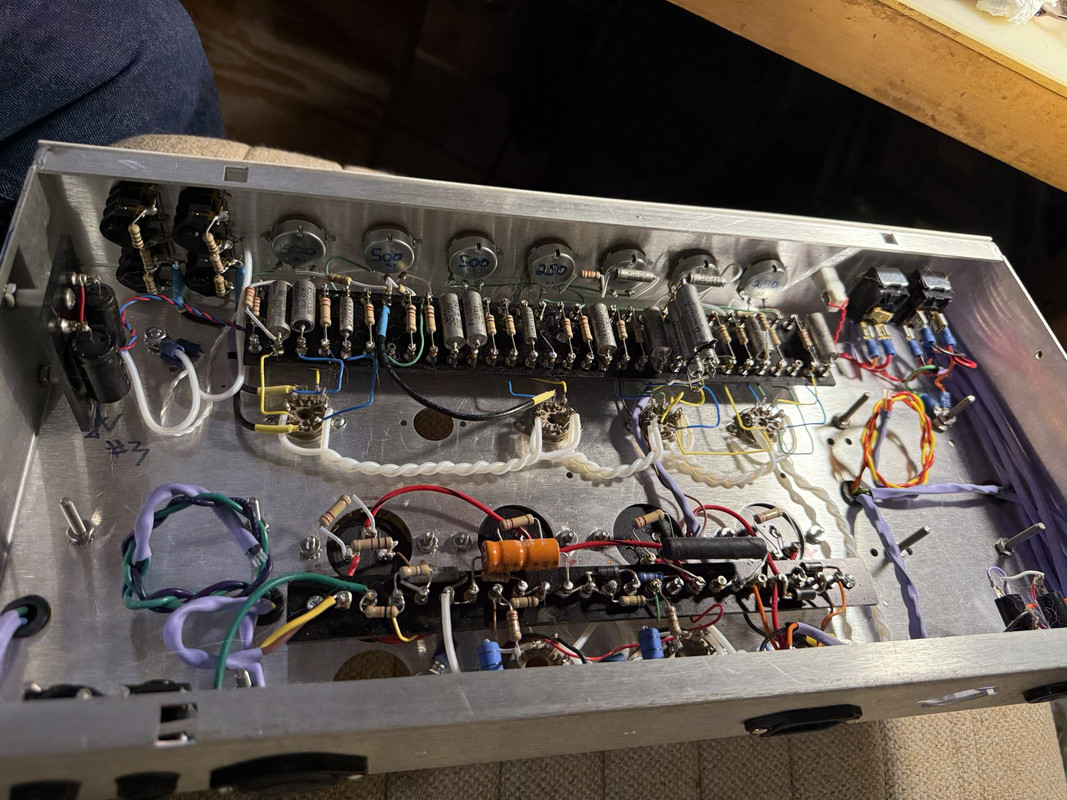
There's old books on building tube amps, can't remember the names but wire dressing is a term. Avoiding closely parallel run wires and making sure that wires that must cross do so at a 90 degree angle. This is one of the reasons I use solid core, so wires don't move. Also using wires that are as short as possible. I measure each length and cut the wire just long enough to strip. This helps to control parasitic oscillation.
I've been building amps for over 20 years, and have built so many 5e3's I lost count. I like to use teflon wire since it is so thin while still having a very high dielectric.
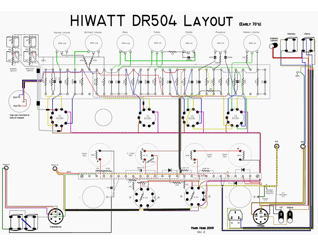
I built six Hiwatt DR504's 17 years ago, not from a kit. A whole lot of sourcing, lol. Sold three to pay for the three I kept. 2 were monoblocks for my JBL JRX125's for vocals and the other for guitar.
I used this layout by Mark Huss when I built them:
(these images are hosted on postimg, and these are hot links. If you click on them it will take you to that site where you can download a full resolution image if you want. I use 210x210 pixels per inch so you can really get good in focus close ups of the details)
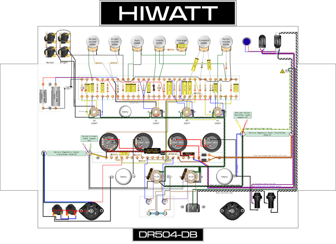
And just yesterday I finished ( I think ) this layout of a DR504 with dual adjustable bias. I traced over a real Hiwatt faceplate at 1000x to make the logo at the top. All of the components I drew using Visio. Particularly happy with the way the 3d jacks came out!
If you look at the layout from mhuss you can see a 22k resistor leading to pin 5 for the bias. My layout just uses a 50k trim pot mounted to the back panel along with test points so biasing with non matched tubes is easy peasy. If the tubes are in spec then the trim pot would just be dialed to 22k and you're there.
And the logo:
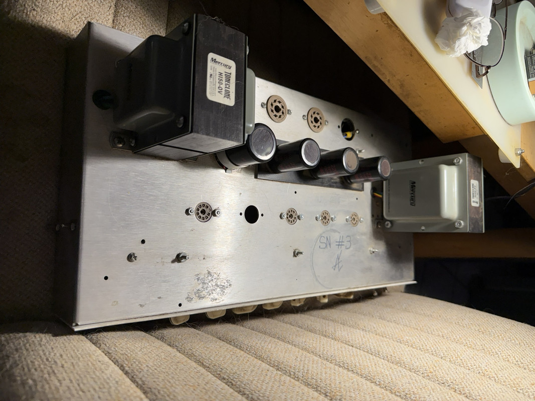
This is number 3. I pulled it out of storage so I could get exact measurements for all the components. My layout is 100% to scale down to the 1/16th of an inch. Since Dave Reeves was English all the measurements are *easy* to measure with a ruler.
") I will add a could of droppers to my next mouser order and try some stuff - separate KT88 screens and plates by 1V more and drop the preamp B rail by 15-16V.
I will add a could of droppers to my next mouser order and try some stuff - separate KT88 screens and plates by 1V more and drop the preamp B rail by 15-16V.