Electrovibe Build w/Monk Mods

I’m just about to start building my first Electrovibe. @Big Monk (or somebody else), can you explain to this idiot what you mean by ”Replace Q1/Q2 with a single MPSA13.” Can I solder in a MPSA13 in Q1 and leave Q2 empty, or what?
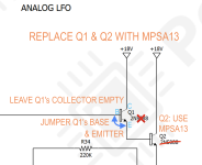
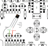
In addition to what you posted...
You'd need to jumper Q2's BASE & EMITTER.


Or you could do it the other way 'round (whichever is easier done on the PCB):


ELECTROVIBE Q1 & Q2 REPLACED BY MPSA13.png
 
I’m just about to start building my first Electrovibe. @Big Monk (or somebody else), can you explain to this idiot what you mean by ”Replace Q1/Q2 with a single MPSA13.” Can I solder in a MPSA13 in Q1 and leave Q2 empty, or what?

I think I would recommend the following if you wanted a good mix of vintage/modern performance:

Q15 = BC547B
Q5, Q6, Q8-Q12 = BC547A
Q14 = BC547C
Q1/Q2, Q3/Q4 = MPSA13

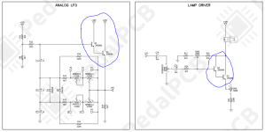
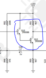
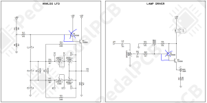
As far as how to install the MPSA13 in place of two transistors, notice how the pairs in question are actually already wired as true darlingtons, as opposed to the pairs in the phaser stages, where on collector has a resistor:

LFO/Bulb Driver:

1780411466595.png

Phase Stages:

1780411491105.png

The easiest way to make the true darlington install would be to make the install of the single darlington into Q2 and Q3, and simply install a jumper wire from base to emitter on Q1 and Q4:

1780411642588.png

Since 2n5088 and MPSA13 both have the same orientation, it should work out like this, and this is how I did it in the past:

1780411860177.png
 
I think I would recommend the following if you wanted a good mix of vintage/modern performance:

Q15 = BC547B
Q5, Q6, Q8-Q12 = BC547A
Q14 = BC547C
Q1/Q2, Q3/Q4 = MPSA13

As far as how to install the MPSA13 in place of two transistors, notice how the pairs in question are actually already wired as true darlingtons, as opposed to the pairs in the phaser stages, where on collector has a resistor:

LFO/Bulb Driver:

View attachment 118178

Phase Stages:

View attachment 118179

The easiest way to make the true darlington install would be to make the install of the single darlington into Q2 and Q3, and simply install a jumper wire from base to emitter on Q1 and Q4:

View attachment 118180

Since 2n5088 and MPSA13 both have the same orientation, it should work out like this, and this is how I did it in the past:

View attachment 118181


I've got a board to do a full size Uni-Vibe and don't feel like trying to spend the time or money to track down vintage transistors. Are the BC547 A, B, C's good modernly available sub for a full size project without hunting down vintage transistors? I see the ones you suggest from Diotec readily available on Digikey right now. Yes, I'm not trying to mod, going as vintage as possible with parts that are readily available.

-Jonathan
 
I've got a board to do a full size Uni-Vibe and don't feel like trying to spend the time or money to track down vintage transistors. Are the BC547 A, B, C's good modernly available sub for a full size project without hunting down vintage transistors? I see the ones you suggest from Diotec readily available on Digikey right now. Yes, I'm not trying to mod, going as vintage as possible with parts that are readily available.

-Jonathan

Yes. I use the Diotec BC547 A,B,C and BC557 A,B,C in everything save for a few projects where I am targeting between 175-215 hFE. They are basically my house transistors.

They go in my Fuzz Faces, Silicon Tone Benders, Powerboost, etc.

They do require some sorting, even within the gain buckets, so if you want a specific value, i'd buy in bulk. They are good to have around anyway.

BC547A breaks down into 200-215 hFE (25%), 215-285 hFE (65%) and > 285 hFE (10%).
BC547B breaks down to pretty much 285-335 hFE (90%) to > 335 hFE (10%)
BC547C is pretty much bang on from 500-550 hFE all the time.

Diotec's consistency is what finally and completely turned me away from NOS silicon. They are also available at Mouser as well.
 
Last edited:
Yes. I use the Diotec BC547 A,B,C and BC557 A,B,C in everything save for a few projects where I am targeting between 175-215 hFE. They are basically my house transistors.

They go in my Fuzz Faces, Silicon Tone Benders, Powerboost, etc.

They do require some sorting, even within the gain buckets, so if you want a specific value, i'd buy in bulk. They are good to have around anyway.

BC547A breaks down into 200-215 hFE (25%), 215-285 hFE (65%) and > 285 hFE (10%).
BC547B breaks down to pretty much 285-335 hFE (90%) to > 335 hFE (10%)
BC547C is pretty much bang on from 500-550 hFE all the time.

Diotec's consistency is what finally and completely turned me away from NOS silicon. They are also available at Mouser as well.
Awesome, thanks for the info! I hope I'm not asking "what's in the secret sauce question", is there a certain tight gain range you're looking for in a Vibe for any of the Q's outside of just the gain bucket?
 
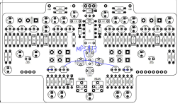
Here's a quick list. Reference the Electrovibe Build Doc Board Image on Page 1 and Schematic on Page 5:

Signal Path:

1.) Tweak R2 if you feel you want more signal gain. 3.3k-4.7k should do the trick. Leave the input divider alone.
2.) Try and hit exact values for the phase caps C12, C18, C25 and C28. Use 5% caps and maybe grab a few of each value.
3.) The original preamp transistors were lower gain than 2N5088. Q1 was a B Gain Bucket and Q2-Q9 were all A Gain Bucket. This is probably "inside baseball" type stuff.

Power Supply:

1.) Ditch the charge pump and feed it 18v directly.
2.) Make sure you use L78L12 for the regulator.

Analog LFO:

1.) Replace Q1/Q2 with a single MPSA13.
2.) Change C8 to 2.2u (MLCC)
3.) Change R14/R15 to taste. Besides potentially locking up the LFO, too fast and it loses all definition. I've gone as low as 1.2k with no issues but 2.2k-3.3k is probably fast enough for anyone.

Lamp Driver:

1.) As always, experiment with Bulbs and LDRs. The Advanced Photonix 9203 LDR from Mouser is pretty good, and all the bulbs in the build doc are good. 2102 and 2174 have more exposed bulb so they tend to "throw" more light.
2.) Replace Q1/Q2 with a single MPSA13.
3.) Use a metallic light shield if you can.
4.) I'd go with either 100 ohm or 200 ohm for the gain trimmer. Just helps tighten up the range of available brightness.
5.) You can experiment with the Offset circuit. 250k is too large. There are too many "deadspots" on the dial and it makes really dialing in good range on the Intensity control more difficult. I use R22 = 47k, Offset = 100k and R26 = 68k.

That's pretty much it.
In regards to changing C8 to an MLCC, so it doesn't have to be polarized then?
 
Yes. I use the Diotec BC547 A,B,C and BC557 A,B,C in everything save for a few projects where I am targeting between 175-215 hFE. They are basically my house transistors.

They go in my Fuzz Faces, Silicon Tone Benders, Powerboost, etc.

They do require some sorting, even within the gain buckets, so if you want a specific value, i'd buy in bulk. They are good to have around anyway.

BC547A breaks down into 200-215 hFE (25%), 215-285 hFE (65%) and > 285 hFE (10%).
BC547B breaks down to pretty much 285-335 hFE (90%) to > 335 hFE (10%)
BC547C is pretty much bang on from 500-550 hFE all the time.

Diotec's consistency is what finally and completely turned me away from NOS silicon. They are also available at Mouser as well.
This might be a silly question, but how much do transistors matter in the univibe?

I've built a few but always used 2088s. Could I use 2n2904s or really NPN here?

My 5088s have about 800hfe that seems high compared to what you are quoting here.
 
Back
Top