Stuff you wanted to know but were afraid to ask

Morning fellas, dumb question alert. I'm sourcing parts for the first time, having only built from kits and in true paint-by-numbers fashion, my knowledge is severely lacking. I'm looking to take a stab at Chuck's Bass Klon and following the *parts list below but have some confusion about the capacitors and their voltages. How do I know which voltage I should be going for? Some caps have 35s, 50s and 100s while others only have 100s and above (on Tayda at least).

Am I right in thinking that I can use just about any of them, as if I'm running the pedal at 9V it won't get close to the max that the caps can handle? I'm thinking I should aim for 35-50 where possible.

*Parts list
View attachment 121358

One of the things not mentioned yet... well, size was mentioned, but not that some caps are the same size regardless of voltage.

Check the physical dimensions of the caps in the datasheets. If you're ordering from Tayda, Mouser, etc they'll often have a link to the datasheet for the part-page you're viewing online.

I have bought Electrolytics in various capacities 16v and 25v and 50v to have all my bases covered — and they were pretty much the same physical size. Given that you want to have some headroom and have caps roughly double the voltage of the pedal...

Let's take 47µ as a prime example — why even bother with 16v if the 35v is the same size and price? The 35v will cover 18v-builds.
Why bother with 35v if you can buy 50v for that extra margin of safety when building a circuit to run at 18v?


47uF 16V 105C Radial Electrolytic Capacitor 5x11mm
47uF 25V 105C Radial Electrolytic Capacitor 5x11mm 2¢ [I usually get 35v]
47uF 50V 105C Radial Electrolytic Capacitor 6.3x11mm

Of course, if you buy higher quality caps, the cost jumps, for example...
47uF 50V 105C Aluminum Electrolytic Capacitor 6.3x11.2mm PANASONIC 17¢

Economies of scale: if you're building commercially, maybe you aren't willing to pay 3¢ per cap when a 2¢ cap will do.
Then there's the issue of quality — do you want to buy a pedal from a builder who cheaps out on electrolytics? The electros will be likely the first thing to go wrong with a pedal down the road. If you're building pedals commercially maybe you want to keep a good reputation and buy some more expensive caps at 17¢ each, bought in bulk bringing the cost down to 16¢ or 15¢ each...

I'm just a hobbyist. I build on the cheap, but I'm willing to pay a penny more per cap to keep one type of 47µ that can cover most any type of build I'll be doing.

Whatever the quality/cost, I don't bother buying 16v caps anymore. It's got to be an EXTREMELY tight layout if you can't squeeze a 6.3mm footprint into a 5mm-space on a PCB.
 
Audio signal still has a lot of mysteries for me, but thankfully there's power supply that makes me feel less like a dumbass (thanks to Valve Wizard).

One of the final things that makes me scratch my head concerns tube rectification: datasheets mention "load resistance" and give me a value (2kohm in my case). But, since I also read about how the series resistor after rectification should be based on the impedance of the secondary supply (to make sure the supply has the highest impedance of the two), I wonder why the datasheet say the tube needs to be 2kohm, it being unaware of the impedance of the transformer used? Does 'load resistance" means something else here?
 
Last edited:
I'm looking to build the Monolith (Big Cheese clone) and Obelisk (Brown Source clone) from AionFx. I'm designing the artwork, but I can't get a clear answer on which direction the 4 modes on the rotary switches are ordered. I've asked Aion but haven't heard back and there doesn't seem to be a clear answer among the build reports and forums posts. Can anyone whose built these circuits confirm if this is the right order or if I need to reverse my labels?
Screenshot 2026-08-30 065854.png


Screenshot 2026-08-30 070049.png
 
I feel like if I tell you anything other than "trace it out with a continuity meter and the schematic" you're not going to learn anything because the answer is right there in the build docs

here's your first clue:
there's only one position where R8 connects to ground (cheese mode) and only one position where the tone pot doesn't connect to C11 (off mode) and they're on opposite ends of the switch rotation. what you need to determine is their orientation on your layout.
 
Last edited:
here's your first clue

I’m hoping to order the rotary switches and cases from Tayda at the same time, so I don’t have one of the rotary switches to test with.

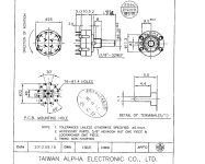
I can look at the schematic and determine which throws corresponds to which mode, but I don’t know if I can determine which rotary position corresponds to which throws. I dont think the data sheet specifies:

IMG_4382.jpeg
 
you have the schematic, the pcb, and the switch data sheet. verify with a multimeter if you want peace of mind because you possess all the necessary information to figure this out yourself.

your second clue is that the switch only turns in one direction through the throws and it's clockwise when looking at the face of the pedal (in industry terms, the control panel face).
 
Last edited:
you have the schematic, the pcb, and the switch data sheet. verify with a multimeter if you want peace of mind because you possess all the necessary information to figure this out yourself.
You may be right. i can verify the order of the modes, but where I’m getting stuck is that without a contact table for the rotary switch (which is not in the data sheet) I don’t see how I can verify whether fully ccw on the rotary corresponds to a1, b1, c1 on the schematic (Cheese mode) or a4, b4, c4 (tone stack bypass mode)
 
you have everything you need, you'd figure it out if you weren't lazy or ignorant. I can solve ignorance real fast. There's no fixing lazy.

According to schematic, A pole has continuity with one pad of C11. Throws A1-3 have continuity with the middle lug of the tone pot. Throw A4 has continuity with one side of both R19 and R20.

According to schematic, B pole has continuity with the other pad of R19 and several other parts. Throws B1 and B2 have continuity with C9 and the others have continuity to nothing.

According to schematic, C pole has continuity with ground. Throw C1 has continuity with one pad of R8. Throws C2-4 have continuity with nothing

So position 1 (A1, B1, C1) is cheese mode and it sweeps clockwise towards Off mode.

You should verify that with a multimeter since you're no longer ignorant and plan on spending money. The problem then becomes a question of your laziness.
 
This thread might give you answers or at least clues.
 
hey look! verification of what I just posted. might as well get flagged for unsportsmanlike conduct since football is back ...

the six connections between the rotary board and main board in no particular order ...
one has continuity to ground (pole c)
one has continuity to the middle lug of the tone pot (throws A1-3)
one has continuity to D2 (pole B)
one has continuity to C11(pole A)
one has continuity to C9 (throws B1-2)
one has continuity to R8 (throw C1)

It's like they included a schematic for a reason.
 
1. Should bias voltage be buffered regardless of PCB placement? I.e. if my VB doesn't appear to be making an antenna on the PCB layout, should you still buffer it?
 
I hate to answer a question with a question but how much current are you drawing that you have meaningful Vb fluctuation?
I'm going off a PCB design suggestion I've found on the forum. There are a lot of engineers who contributed to that thread, and I'm sure that in more sophisticated circuits it's mission critical, but for a sharp dressed YATS, I have my doubts.

I've got an extra opamp stage and rather than terminate it per the TI white paper, maybe it would be beneficial doing some work.
 
Back
Top