Strategies for LED offboard wiring?

giovanni

Well-known member
Hey guys, I typically try to line up the LED bezel with the LED position on the PCB so I can just pop it in the bezel and solder it in. However, I won't be able to do that for a few builds I am working on (LED too close to pots/switches) so I am going to just wire it offboard. I have seen people do that all the time but I wonder: how do you solder wire to the LED leads? Just hold them together and apply solder? Or do you use some sort of fancy connector or something? Fishing for ideas! Thank you!
 
I strip back enough wire to get one wrap around the LED leg and solder together (helping hands are pretty much required), clip the LED leg, and then wrap it all in heat shrink tubing.

If you search eBay or Amazon for “pre wired LED” you’ll find LEDs that already have all of this done already, too! They even usually have a current-limiting resistor too, so you’d just jumper the CLR on the board
 
I use blue tack for basically everything, including this. Just hold the two things in place, add a drop of solder et voila c'est tout.
 
I hold the LED with helping hands, tin the legs and wires. Then just hold the wire onto the leg and apply the tip.

I also socket the LED because I’m still a novice.
 
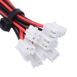
I have soldered wires (and resistors) to LEDs, but what I've also done is wire up a JST XH connector to the LED space on the board and simply plug the LED into the holes in the plug. Works perfectly, and you can swap different LEDs in and out. Of course, this only works if the resistor for the LED is on the PCB.
 

Attachments

  • st.jpg
    st.jpg
    241.8 KB · Views: 8
I have soldered wires (and resistors) to LEDs, but what I've also done is wire up a JST XH connector to the LED space on the board and simply plug the LED into the holes in the plug. Works perfectly, and you can swap different LEDs in and out. Of course, this only works if the resistor for the LED is on the PCB.
That's a cool idea!
 
Back
Top