- Build Rating
- 5.00 star(s)
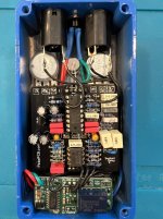
Here are my second and third builds of the Seabed Delay. As I mentioned in the build report for my first Seabed, I originally intended to build two of these circuits into a single enclosure. When I went to order the pair, I forgot that I'd previously already ordered a single! I populated all three PCBs in parallel, but was much slower getting them boxed up.
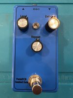
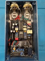
Number two is very similar to the first: it's also crammed into the smaller 1590B enclosure, with top-mounted jacks. I found the topside I/O 1590B arrangement to be a short-lived interest of mine. Initially, I was drawn to the board space-savings. But I've since decided to prioritize ergonomics (or, more accurately, to try to save myself from my clumsiness), and focus on a "less is more" approach to the pedalboard. Additionally, I found that it becomes impractical, if not impossible, to use pancake-style patch cables with top-mounted jacks, because they will block access to the power jack. It also uses the SMD version of my microcontroller-based relay bypass.
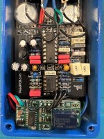
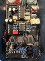
Number three made it into a "Brunken Blue" 125B from @StompBoxParts (who deserves special thanks for fixing a recent order that I messed up). I used the same graphics for #3 as I did for #1. Number three uses my newer, super simple CMOS-based relay bypass scheme.
All three worked great on first power-on.
Number two is very similar to the first: it's also crammed into the smaller 1590B enclosure, with top-mounted jacks. I found the topside I/O 1590B arrangement to be a short-lived interest of mine. Initially, I was drawn to the board space-savings. But I've since decided to prioritize ergonomics (or, more accurately, to try to save myself from my clumsiness), and focus on a "less is more" approach to the pedalboard. Additionally, I found that it becomes impractical, if not impossible, to use pancake-style patch cables with top-mounted jacks, because they will block access to the power jack. It also uses the SMD version of my microcontroller-based relay bypass.
Number three made it into a "Brunken Blue" 125B from @StompBoxParts (who deserves special thanks for fixing a recent order that I messed up). I used the same graphics for #3 as I did for #1. Number three uses my newer, super simple CMOS-based relay bypass scheme.
All three worked great on first power-on.