SOLVED Magnetron - Bypass and Dry signal but no delay

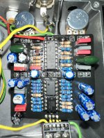
I've just put together a Magetron, and as per the title I'm not getting any delay - bypass signal passes, and I get dry signal with the effect on, but no delays.
The modulation appears to be working, as the rate LED and I can faintly hear it doing something in the background.

At first it was making a ticking noise that was affected by the level and time controls, but not feedback - this has gone away after reflowing multiple solder joints though.
I've verified the pt2399 works as does so in another circuit (spirit box).
The internal gain knob also does appear to affect signal level.
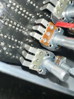
Lower row of pots all have covers.
Pics below - any ideas or tips where/how to probe?


EDIT/UPDOOT: Found a solder bridge under an electrolytic - after fixing I now get one very quiet repeat, but that's all.
 

Attachments

  • 449402734_1150383962659262_4445760016869714494_n (1).jpg
    449402734_1150383962659262_4445760016869714494_n (1).jpg
    565.4 KB · Views: 14
  • 449403454_1031539285076419_5933103052162612490_n.jpg
    449403454_1031539285076419_5933103052162612490_n.jpg
    503.1 KB · Views: 15
  • 449888643_968362488360733_8449320975538857536_n.jpg
    449888643_968362488360733_8449320975538857536_n.jpg
    481.5 KB · Views: 11
  • 449903762_469989042300613_1840616920689189761_n.jpg
    449903762_469989042300613_1840616920689189761_n.jpg
    274.5 KB · Views: 10
  • 450391162_789103429949732_890164553704133363_n.jpg
    450391162_789103429949732_890164553704133363_n.jpg
    388.9 KB · Views: 14
Last edited:
Update: Found a solder bridge under an electrolytic - after fixing I now get one very quiet repeat, but that's all.
I've done some probing based on other threads and the following for additional info:

Feedback pot to C3 does measure 11k
All pots measure/work correctly
I can trace continuity through R4 -> C3 -> R8 -> R9 -> Feedback pot
I can trace continuity through IC Pin 12 -> R13 -> R15 -> IC Pin 13 -> Pin 14 -> Feedback pot
 
scrub the board and take a picture without the flash, it makes orange look red etc. I can see a few wrong values but I don't know for sure. C17 for starters. Or is it C14? The build docs are different from the picture on the main page...paging @Robert :ROFLMAO:
 
R17 -15K should be BROWN GREEN BLACK RED BROWN ???
We have a bingo! A gremlin apparently replaced my 15k resistors with 1.5k (it's me, I'm the gremlin)

It now works, has far less repeats than it should (not any where near oscillation) but it works. The repeats will likely be corrected by...

scrub the board and take a picture without the flash, it makes orange look red etc. I can see a few wrong values but I don't know for sure. C17 for starters. Or is it C14? The build docs are different from the picture on the main page...paging @Robert

AHAH! It's 33n but should be 330n... I gotta stop mathing these out in my head. I'll try to pickup a substitute tomorrow and see if that fixes things. (The PCB silkscreen says 330n so I'm guessing it's c14.)
 
We have a bingo! A gremlin apparently replaced my 15k resistors with 1.5k (it's me, I'm the gremlin)

It now works, has far less repeats than it should (not any where near oscillation) but it works. The repeats will likely be corrected by...


AHAH! It's 33n but should be 330n... I gotta stop mathing these out in my head. I'll try to pickup a substitute tomorrow and see if that fixes things. (The PCB silkscreen says 330n so I'm guessing it's c14.)
I never trust myself doing the math in my head!
 
Right! So replacing the 33n with the correct 330n has resulted in much longer and more expected delay times.

But now I have no modulation for some reason. Which worked fine before. Agaaghhghgdfsdds.

Any ideas?
 
Did you clean your board? Could just be stray solder splatter messing things up.
Yep. Gave it a thorough clean with iso alcohol. Also tried replacing the depth pot & led + subbed the LM258n for a TL072 incase that was fried and still no dice. The modulation LED isn't going either so my guess is it's LFO related, but I can't make sense of the LFO in the schematic (I am not a smart man).
 
Yep. Gave it a thorough clean with iso alcohol. Also tried replacing the depth pot & led + subbed the LM258n for a TL072 incase that was fried and still no dice. The modulation LED isn't going either so my guess is it's LFO related, but I can't make sense of the LFO in the schematic (I am not a smart man).


Check all values and continuity in this area. Voltages on the IC etc too. Stop replacing stuff lol

lfo.png
 
Continuity was broken between C8 & the depth pot somehow. probably severed the trace internally with all my poking, prodding and bending pots back and forth, but a jumper solved it.

Protip: populating boards while watching youtube and hitting cones is a bad idea and a sign of overconfidence.

But, I officially declare this solved! Thanks all.
 
Back
Top