Can't find a post/tutorial

phantom

Member
When I first started looking around here I came across a post of a pedal being assembled, and in what order components are put on the board. I can not for the life of me find it now. I have tried the beach function but with no luck.
It started with installing pots first I believe. I am more familiar with automotive sites.
Thank you
 
I would normally do pots last.

Stuff on the board goes in size order - smallest to largest height. Resistors first, working up to electrolytic caps. I like to mount the pots in the enclosure, then solder to the board so I know they're lined up nice to my drill holes.

Jason at Fuzzlord effects has some good videos on the basic steps of putting a pedal together. I think the height order thing is pretty standard, but one of his videos was the first place I saw it mentioned.

 
When I first started looking around here I came across a post of a pedal being assembled, and in what order components are put on the board. I can not for the life of me find it now. I have tried the beach function but with no luck.
It started with installing pots first I believe. I am more familiar with automotive sites.
Thank you
Was this it?
 
Was this it?
Yes this is the one. I searched and searched.
 
I would normally do pots last.

Stuff on the board goes in size order - smallest to largest height. Resistors first, working up to electrolytic caps. I like to mount the pots in the enclosure, then solder to the board so I know they're lined up nice to my drill holes.

Jason at Fuzzlord effects has some good videos on the basic steps of putting a pedal together. I think the height order thing is pretty standard, but one of his videos was the first place I saw it mentioned.

Thank you, I will definitely check that out !
 
My work flow is:
Resistors one at a time
Diodes
Any IC or transistor sockets that I'm putting in
Film Caps/Ceramic caps
Electrolytic caps
Wash/brush the pcb with 99% isopropyl
I then bend the two outer legs of pots outwards.. put insulators on their backs.. place in the pcb and solder one lug to keep it there
Then I drill my enclosures... Dry fit the pcb to make sure everything is lining up
Next I solder all my offboard power, switch and jack wires to the pcb longer than needed.. then I clean my flux again
Then I fit my led into pcb and bend the ends of the leads so it doesn't drop out..
Install pcb into my now painted/decorated enclosure and line up led in its bezel or hole... install a few pot nuts to keep pcb steady.
install power jack
install foot switch
Wire power jack neatly and with as little wire as possible
Wire in my footswitch and keep the wiring tidy
Solder in the rest of the pot lugs and re touch the original joint.
Install input / output jacks and wire them in..
Clean any flux once again with qtips and alcohol as I go
Install IC chips
Then I plug it up and give it a quick test on my bench amp to see if it's allgood..... then I go put it on my board and give it a real test drive.. Viola!

Side note..... I have run into problems with my builds not working many times, so now part of my process is I have a component tester on my bench and I literally test every resistor, transistor,diode and capacitor before I place/solder.. then I measure every pot's resistance with a multimeter to make sure it's sweeping correctly.. especially trim pots!.. had found several in my orders the past 2 years that were duds. This way I know I've tested the components and anything not working is likely my soldering and possibly a pcb issue.. which is highly highly unlikely.
That's a really good tip to check all the components before soldering them in.
 
My work flow is:
Resistors one at a time
Diodes
Any IC or transistor sockets that I'm putting in
Film Caps/Ceramic caps
Electrolytic caps
Wash/brush the pcb with 99% isopropyl
I then bend the two outer legs of pots outwards.. put insulators on their backs.. place in the pcb and solder one lug to keep it there
Then I drill my enclosures... Dry fit the pcb to make sure everything is lining up
Next I solder all my offboard power, switch and jack wires to the pcb longer than needed.. then I clean my flux again
Then I fit my led into pcb and bend the ends of the leads so it doesn't drop out..
Install pcb into my now painted/decorated enclosure and line up led in its bezel or hole... install a few pot nuts to keep pcb steady.
install power jack
install foot switch
Wire power jack neatly and with as little wire as possible
Wire in my footswitch and keep the wiring tidy
Solder in the rest of the pot lugs and re touch the original joint.
Install input / output jacks and wire them in..
Clean any flux once again with qtips and alcohol as I go
Install IC chips
Then I plug it up and give it a quick test on my bench amp to see if it's allgood..... then I go put it on my board and give it a real test drive.. Viola!

Side note..... I have run into problems with my builds not working many times, so now part of my process is I have a component tester on my bench and I literally test every resistor, transistor,diode and capacitor before I place/solder.. then I measure every pot's resistance with a multimeter to make sure it's sweeping correctly.. especially trim pots!.. had found several in my orders the past 2 years that were duds. This way I know I've tested the components and anything not working is likely my soldering and possibly a pcb issue.. which is highly highly unlikely.
On resistors, you mean all of one value at a time, I suspect? :)
 
On resistors, you mean all of one value at a time, I suspect? :)
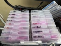
yeah... i generally start at the lowest value and populate all of them in that value and work my way up... My box i keep for resistors is laid out that way so I can flip through them quickly... I use a bin that holds clear tackle box type boxes that are small enough to hold about 20 packs of 100... i label the boxes with the range that in each box... makes it super quick to find what I need....
 
Back
Top