DougieFresh
New member
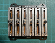
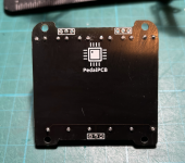
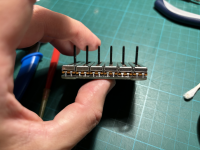
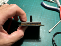
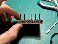
I've encountered a very frustrating issue with the leftmost (100 Hz) slider pot and I've completely run out of ideas. After assembling everything and soldering the potentiometer and main boards together, I noticed that the leftmost pot was not boosting the low frequencies as expected when above the midpoint. When I would gently flex the shaft of the pot to the RIGHT (towards the other pots) while sliding it up and down, it worked fine, but otherwise it wasn't working properly. I verified later that it also appeared to work correctly when I applied pressure to the housing of the pot in the same direction (to the right, by gently squeezing the row of pots together with my hand) rather than flexing at the shaft.
Here's what I've done so far to troubleshoot:
- Verified that there was no contact between the pots and the enclosure. The problem persists with the boards completely out of the enclosure.
- Verified that the pots were sitting flush and even in the PCB, and that they were not touching each other or the PCB in a weird way.
- Separated the two boards and verified all solder connections on the potentiometer board (pots and pin headers), ensuring there was no excessive flux (removed with alcohol), no bridges and reflowing all solder joints.
- Tested the pots using the pin-headers. Other than the 100 Hz one, the pots all showed smooth changes in resistance along their travel length. The values were not at all what I expected (going from 0 at one end to 15k at the midpoint, and then going back DOWN to 10k on the other end...), but I presume that's from the way they are connected to each other? In any case, they were functioning normally in the circuit so I presume this is not an issue. For the 100 Hz pot, however, I noticed the values were different, ranging from 10k to 60k from one end to the other, unless I flex the shaft to the right, in which case I see the same values as the others. So at this point it seems obvious that the problem is a janky pot, right?? Nope!
- I removed the 100 Hz pot and tested it. When not connected, it seems to work perfectly, smoothly ranging from 0 to 50k without any weirdness even when I torqued the shaft to the left or right, or when applying pressure in different ways to the housing. I re-installed it, and the problem re-appeared.
- To be extra sure the problem is not with the pot, I removed it again and then also removed the rightmost pot (3.2 kHz) that was working perfectly before, and I swapped them. Lo and behold the same issue occurs with the (new) 100 Hz slider.
So now I'm at a complete loss and have not clear sense of what to try next. As always, any help is greatly appreciated!!


