A simple Relay Bypass

Chuck D. Bones

Circuit Wizard
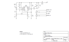
This is a variation on the 555-based Relay Bypass Board sold here. This circuit drives a 5V relay, or any other coil voltage up to 9V. No regulator is required. I made the best use of the output pins by using the DISCHARGE pin to drive the relay. The DISCHARGE pin has higher current sinking capability than the OUT pin. This circuit can be used stand-alone, or integrated into a pedal circuit board.
Chuck's Relay Driver v1.1.png

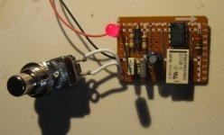
Chuck's Relay Driver 02.jpg
 
Interesting.. I was contemplating making something similar to 1 of our esteemed members schmorg but hand operated( I play seated) and it IS easier/cheaper to get light touch momentary spst push buttons than 3pdt toggles. what changes would be needed for a 12/18v effect?
 
It's doable, but it's not all that simple if you only have 18V available. You can't power a 555 directly from 18V because 555s are rated for 16V max. If you can power the 555 from 12V, then it's simply a matter of increasing R4 to the appropriate value, based on relay coil resistance.
 
Interesting.. I was contemplating making something similar to 1 of our esteemed members schmorg but hand operated( I play seated) and it IS easier/cheaper to get light touch momentary spst push buttons than 3pdt toggles. what changes would be needed for a 12/18v effect?
One thing to keep in mind with hand-operated pedals is that you don’t necessarily benefit from an LED when using a toggle switch as the direction of the switch itself serves as an indicator. I use these for all of my hand-operated pedals (for keys and console steel guitar), and they’re much cheaper than the combined cost of a momentary push button and a relay:
https://lovemyswitches.com/taiway-dpdt-on-on-switch-solder-lug-long-shaft-big-bat/
 
Really great stuff! This is greatly appreciated.
If you can power the 555 from 12V, then it's simply a matter of increasing R4 to the appropriate value, based on relay coil resistance.
Would you be able to elaborate on the relationship with R4, coil resistance, and operating voltage?

For example, I am looking at the FTR-B4CA, which is 4.5V with 145 ohm resistance. How does this change at 9v and 18v?


Never mind! I did work that out and learned to trust the spec sheet and not the reseller website for supply voltage.
 
Last edited:
I'm testing this circuit on a breadboard now. With 9V supply and NA5W-K it draws around 3mA when Off and 30mA On (including 3mA for the status LED),
Looks like 270R is the upper limit for R4. With higher value ofthe R4, coil supply voltage drops below 3.5V and relay won't turn on. And with 270R R4 we gain only 3mA.
edit - 270R for 9V supply and NA5W-K.
 
Last edited:
Really great stuff! This is greatly appreciated.

ICM7555 is rated for 18v, so this could be an option of a 9-18v component. Would the NE555 be an option as well?

Would you be able to elaborate on the relationship with R4, coil resistance, and operating voltage?

For example, I am looking at the FTR-B4CA, which is 4.5V with 145 ohm resistance. How does this change at 9v and 18v?
From the rated coil resistance and coil voltage, we calculate the coil current. Now we subtract the rated coil voltage and the 555 voltage drop (about 0.2V) from the rail voltage. That gives us the desired voltage drop across R4. Finally, we divide that voltage by the coil current and then round-off to the nearest standard value to get R4.
 
You mean this?
Some explanations are in order:
The red X's mark the locations of cuts. Those are the only places you need to cut.
The links under IC1 & K1 are diagonal. It was the cleanest way to make the connections. Clever or sloppy? You decide.
A section of the 4th, 5th & 6th columns are joined by solder bridges (or bent over leads) on the solder side of the board to create the large red rectangle. Most people do it with jumpers, but those take up space.
I did a similar thing to create the small pink rectangle.
I ended up using a 1N4148 for D1 because a 1N5817 is too large to squeeze between the IC and relay.
Select a resistor value for RLED that gives the desired LED brightness.
Select a resistor value for R4 that gives the desired relay coil current. I describe the formula above. R4 should be 1/4W. My schematic shows 150Ω, which is the nearest common value. I installed 130Ω because I had one and it is closer to the ideal 135Ω value for my relay.

1679867371408.png
 
I have a ton of them. This will be fun! Correct me if I’m wrong but this isn’t using a “flip flop” debouncer right? You need transistors to do that correct? Or am I just completely wrong here lol
 
The 555 is full of transistors. At its heart are two comparators and a flip-flop. The comparators inputs are tied to the TRESHOLD and TRIGGER pins inside the IC. We connect TRIGGER & THRESHOLD to 1/2Vcc (R2 & R3) outside the IC. The output pin either charges C2 to 9V (if the flip-flop is in the SET state), or discharges C1 to GND (if the flip-flop is in the RESET state). R1 & C1 form a delay. Whenever the flip-flop changes state, they briefly remember the flip-flop's previous state. When we press the stomp switch, we connect C1 to the TRIGGER & THRESHOLD pins. This yanks the TRIGGER & THRESHOLD pins either above the Threshold comparator's threshold, or below the Trigger comparator's threshold. Whichever happens, one of the comparators commands the flip-flop to go to the opposite state. C1 & C2 provide some noise filtering, but the flip-flop is the debouncer. There's a little more trickery going on, but that's the basics.
 
Thanks @Chuck D. Bones - I will definitely give this a try. I often use the coda bypass and get an odd intermittent pop with some builds.

This should be known as Celestial Switching.

Aw c'mon. It's not my circuit. I just took somebody else's circuit and tweaked it a little bit.

The Coda is a clever relay controller and it has a mute pin on it that can be tied to a FET or opto-coupler that briefly mutes the output while the relay flips to the other state. I have some boards with the Coda controller on it. I don't use the mute function and so far have been lucky. You have to use a low-current relay if you drive it directly from the PIC because the PIC can't source or sink much current. For my purposes, the 555 is more practical.
 
Had to read that a few times to get a grasp of that but i think i somewhat understand. I think breadboarding it will help me get it a bit better. I know what tomorrows agenda is!
 
What are the pros/cons/differences between this and the PPCB circuit? Both are past my understanding of circuits, so other than the lack of a need of a regulator, I'm not sure of the differences.
 
Back
Top