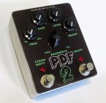
Acrobat Parametric Distortion

If you're interested in filters with distortions like this, the other one to look at is the Systech Harmonic Energizer, and there is a schematic for that one. I can't speak to how similar it is, but it is a very viable circuit, and it has similar controls. I'd say the distortion isn't quite as viable as the PDF-2, but it sounds quite nice going into something else

Recently put into a combo pedal for Matt "I love cocked wah" Pike with a high gain preamp circuit by Does it Doom.
I've heard of that one before.
I'm mainly wondering how to improve the sweep of the PDF Filter height control, cause I can't find a 10kW or 10kS taper pot anywhere and clearly this one uses a 10k dual linear so idk if it's using it's other half to change it's own taper and get more control at the extents of the travel.
 
Hi everyone,


I’m trying to verify one small detail of the Acrobat circuit and I was wondering if anyone who has built one — or has an unpopulated PCB / board on the bench — could help me confirm it.


I’m specifically interested in the dual B10K HEIGHT potentiometer.


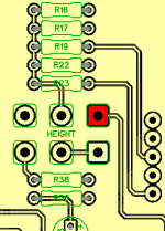
Looking at the potentiometer from the lug side, could someone confirm:


  • which HEIGHT pads/lugs are connected to R38;
  • which are connected to R18 / R23 / R25;
  • whether two lugs of either gang are directly connected together on the PCB.

Even better, if someone has an Acrobat available and a multimeter, I’d be extremely grateful for a resistance measurement of the two HEIGHT gangs at three knob positions:


full CCW / approximately noon / full CW


For each gang, measuring:


  • lug 1 ↔ wiper (lug 2)
  • wiper (lug 2) ↔ lug 3

The pedal should of course be powered off for resistance measurements.


I’m particularly interested in the electrical orientation of the two gangs, so I’d rather not suggest what result I’m expecting.


Photos of an unpopulated PCB around the HEIGHT footprint would also be very useful.


Thanks a lot!
 
Thanks! That confirms the topology I was looking at. The only detail I’m still missing is the physical orientation of the HEIGHT dual pot.

If anyone has an Acrobat and a multimeter, could you measure resistance between lug 3 and the wiper (lug 2) of the gang connected to R38, with the pedal powered off, at full CCW and full CW?

Just those two resistance readings would completely answer the question. Thanks!
 
Pad highlighted in red connects to R18 (offscreen)

View attachment 125655

Thanks Robert, that’s very helpful — especially for establishing the physical pad orientation.


The last thing I’m trying to determine is which end of the actual dual pot track corresponds to each end of rotation. If you have an assembled Acrobat, could you measure the resistance between lug 3 and the wiper (lug 2) of the gang connected to R38, at full CCW and full CW, with the pedal powered off?


Just the two resistance readings would settle it completely. Thanks!
 
Around 10.32 k ohms at full ccw
Around 2 ohms at full cw

This is for pins 3 to 2 and applies to both gangs (left and center pins, looking solder-side; the readings are the inverse for the right and center or pins 1 to 2).
Thanks Robert, that’s very helpful — especially for establishing the physical pad orientation.


The last thing I’m trying to determine is which end of the actual dual pot track corresponds to each end of rotation. If you have an assembled Acrobat, could you measure the resistance between lug 3 and the wiper (lug 2) of the gang connected to R38, at full CCW and full CW, with the pedal powered off?
 
A quick follow-up question about the Acrobat’s dual B10K Height potentiometer.
A previous measurement confirmed approximately 10.32K between lug 3 and the wiper at full CCW, and almost 0 ohms at full CW.
Would it be possible to measure the same resistance at approximately 12 o’clock and 3 o’clock?
I’m particularly interested in whether both gangs behave linearly throughout the rotation.
This would help distinguish the actual potentiometer behavior from the nonlinear response produced by the surrounding circuit.
Thanks again!
 
and last one..
I’m studying the Acrobat PCB134 circuit and trying to verify the exact wiring of the dual-pole Bandwidth rotary switch.
From the schematic and PCB photos, I’ve reconstructed the following possible pairings :
PositionPole APole B
1680ROpen
2470R100K
3330R20K
4150R10K
51R4K7

Could anyone who has built the Acrobat confirm whether these pairings are correct?
In particular, I’m trying to verify the connections from R24 (100K) and R27 (10K) to the rotary switch breakout board.
A clear photo of the rotary breakout board, or a continuity check, would be incredibly helpful.
I’m working on a circuit-based digital model and want to avoid making assumptions about connections hidden beneath the PCB.
Thanks very much!
I can pretty much guarantee that the connections will not be different than what is on the schematic, and if they are, then we have a problem.

What are you trying to figure out with the B10K? Shouldn't a digital model of the circuit behave the same as an in-circuit B10K?
 
I can pretty much guarantee that the connections will not be different than what is on the schematic, and if they are, then we have a problem.

What are you trying to figure out with the B10K? Shouldn't a digital model of the circuit behave the same as an in-circuit B10K?

Thanks for the clarification!


I agree — a properly implemented circuit model should reproduce the behaviour of an in-circuit B10K potentiometer.


I’m not questioning the B10K itself. I’m trying to verify that both gangs of the Height control are represented correctly, including their connections, orientation and interaction with the surrounding filter network.


The digital model is based on the Acrobat schematic and a SPICE reconstruction. It already reproduces the expected cut/boost behaviour, but I’m investigating the rather large output-level variations across Height, Frequency and Bandwidth.


I understand that substantial level changes may be inherent to the original circuit, so I’m not assuming they’re a modelling error.


I’m also developing an optional, post-circuit Auto Level feature to make the plugin easier to use in a mix without changing the actual filter or distortion behaviour.


Regarding the rotary switch, I agree that the PCB should follow the schematic. I was simply hoping to independently verify the exact resistor-to-position assignments, since some of the traces are hidden beneath the assembled board.


Thanks again for your help!
 
Back
Top