Bobb Lobblaw
New member
Hello All..longtime lurker, first-time poster. Wholy appreciate any help offered.
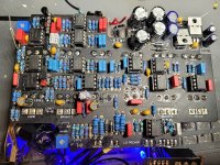
OK..So I built this L5 beast and boxed it before I rocked it (yeah, I know. I just really needed to see the cool knobs I bought for it in place at that exact moment). Fired it up and got a big buzz and a choked & very faint signal. But with the Master and Channel Vol. cranked I could hear all the knobs and switches doing their jobs...Even the Multifilter was multifiltering.
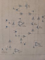
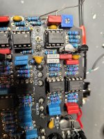
Checking the Voltages, vs. those posted by The Creator, they are ALL good, except pin 6 of IC10 a CA3080 for the comp/limit...I should be getting .9v and I'm getting the nearly full 15v regardless of whether the 3080 is in the socket. Pin 6 is also attached to a couple of transistors (2N5088s) QX1 & QX2 and a distortion trimmer, which are also giving me the same high voltage. Here are the most recent readings (my #s are in parenthesis).
IC10 CA3080E
1 = 0 (0) 8 = 0 (0)
2 = 0 (0) 7 = 14.73 (14.87)
3 = 0 (0) 6 = 0.9 (14.02)
4 = -15.2 (-15.07) 5 = -14.5 (-14.38)
QX1
1 = 0.4 (13.35)
2 = 0.9 (14.03)
3 = 14.66 (13.33)
QX2
1 = -0.22 (12.60)
2 = 0.4 (13.33)
3 = 13.21 (12.59)
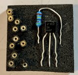
I assume the transistor readings are wacky because P6 is passing all the power along the circuit. I saw a similar issue in THIS thread, and the answer was fake 3080s, but I got mine at Smallbear ($7!), so I would hope they're authentic. Perhaps there's a subtle but significant pinout difference between 3080AE's (the ones I bought) and the other versions 3080A etc..? but I don't think so...same datasheet
Likewise, tracing the audio signal, everything is fine through both Channels, and the Multifilter, all of which are then fed to the Master Vol/Comp/Output. All the other chips, pots, and switches have a signal. Messing with the dist & comp trimmers has no effect either. But I get to IC10, and Boom! A diminished and distorted signal from P6 and QX1/Qx2. The Master Vol. signal is also faint and ugly
I've tried reflowing the socket, no change. I've tried switching out the 3080 in IC11, thinking (hoping) that perhaps one of them was bad..same thing.
I'm not sure what to try next. Should I try another set of 3080's? If Smallbear's supply is tainted with fakes, where can I get some real ones?
Is it odd that all the voltages on every other pin on IC10/3080 are good except P6 with or without the IC slotted?
I'd really like to put this on my board..not to mention the ego boost for getting this Beautiful Behemoth up and rockin'. Thanks again, for any assistance! (sorry for the crappy photos and I know I need to clean the PCB a bit)


