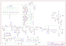
Can someone help with this tube screamer schematic?

neiltheseal

Active member
Hey

I've been working on a Tube Screamer circuit with all of the mods. I posted about it on this thread but I have clearly bitten off more than I can chew.

I have put it together and it passes signal so that's a win, however there is no gain. With an audio probe I have tracked the problem to IC1.1. The signal enters strong on pin 3 but comes out extremely weak from pin 1 and therafter.

I measured the voltages and they are as follows:
  1. 7.8
  2. 7.8
  3. 0.2
  4. 0
  5. 7.6
  6. 7.6
  7. 7.6
  8. 8.6
This seems to confirm the problem is here as I assume that pins 1,2,3,5,6 and 7 should be about 4.5v.

I put a bias trimmer going intyo pin 3 of IC1. The scematic says 1m but I only had a 470k trimmer. The trimmer celarly affects the circuit and I can get some cool tremolo sounds at some settings or splatty fuzz. But still it's too quiet and not clipping.

Does anyone have an idea what I have done wrong here? Any help is appreciated.
Screen Shot 2024-02-29 at 4.06.04 pm.png
 
One thing that stands out to me is the gain and band clips are connected to Vref and not ground. I took this idea from the stockade but other TS schematcs have this connected to ground. Should this matter?
 
  1. As drawn, The BUFFER.1 switch will kill the signal in the "non-buffer" position.
  2. As drawn, The BUFFER.2 switch will kill the signal in the "non-buffer" position.
  3. LOCUT should return to Vref, not GND. As drawn it will mess up the biasing for IC1.1.*
  4. The LOCUT knob's range will change when you flip the MID switch.
  5. You don't need R5 and the BIAS trim once you correct #2.
  6. Ge diodes D21-D24 are leaky and will severely limit the gain.
  7. The BRIGHT pot is should be 10K.
  8. The BRIGHT pot is wired so that as your turn it CW, the tone gets darker. Maybe rename it "HICUT."
  9. You won't hear any difference when you switch the 808/TS9 switch.
  10. The BOOST pot will have a better sweep if it's C-taper.
  11. You should have a bypass cap connecting IC3-1 to GND.
Returning the R8 to Vref or GND is ok either way. I prefer GND.

LOCUT and BAND do pretty-much the same thing. I'd ditch the BAND switch and just use C28. There is a subtle difference between BAND & LOCUT when DRIVE is dialed down; try them and you'll see what I mean.

Is R28 1K or 7.5K?

* When you correct #3, you should also increase R29 to 47K and LOCUT to C500K so that you don't disturb Vref when LOCUT is dimed. Decrease C2 and C20 to 4.7nF.
 
Thanks chuck for entertaining my stupid ideas! Your feedback is appreciated. I’ll try these out today and over the weekend.

R28 is 7k5.

Why will the buffer switch kill the signal in the non buffer position? Is it because the power supply is cut off in the non buffer position?

You are right by the way. There is enough signal for me to notice that.

I know all/most of these changes are redundant. I’m just curious to see what I do and don’t like but I don’t really enjoy breadboarding. Thanks again
 
RE the compensating cap for IC3. Do you mean I should connect Pin 1 to ground? Would a 100uf electro cap do the trick? It does pop when I flick the switch and it takes a while to change voltage.

I did put this together but it clearly isn't working as I had hoped. I might make a version 2 that is more simplified based on your suggestions @Chuck D. Bones.
 
A bypass cap is needed at the input to IC3 to minimize RF noise. IC3 runs at 40KHz or so and while you cannot heat that, you will hear the effects if it interferes with sampled devices like the FV-1, PT2399, BBDs, etc. 100uF from pin 1 & 8 to GND will do the trick.

It's gonna pop when you change Vcc from 9V to 18V or vice-versa, that's normal. You should only do that on rare occasion, if ever. I question the utility of running a TS on 18V. There should be plenty of headroom with Vcc = 9V.

I understand that this is an experiment to find out what features work and don't work in a TS. We'll be interested to hear your findings on the various clipping and EQ options. I got kinda crazy myself playing with TS mods.
 
Back
Top