SOLVED Aion Xenotron / Lovetone Flange no BBD modulation

Kris100

Member
Hey, hope I can ask you All for a bit of help and / or advice - Finished this build yesterday... and surprise surprise it doesn't work :) I've built 150+ pedals and never ended up with a build that doesnt work (including couple Aion Lovetone builds) so I really hope I can get this one working as well.

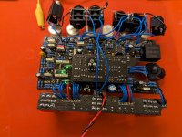
Pedal has 3 separate 3PDT's where 1 is for the effects loop, 1 for time modulation and 1 for space modulation. Time and space LEDs follow rate of modulation set by the pot. There are several internal LED / LDR combo - 2LED / LDRs for the Space on the main PCB, 1 LED / LDR for Time and additional LED / LDR for time on the BBD sub board.

3PDT LEDs light up, space and time ones pulse in tempo with the rate, SPDT switches seems to work, pedal passes signal through but there is no BBD LFO modulation. Space switch engaged works as a tremolo but Time doesn't seem to create any chorus / flange modulations. When I max out Manual control I can get some weird faint modulations with the internal BBD trimpot tweaked right but nothing that resembles typical chorus / flange vibes.

In terms of troubleshooting - I checked IC orientation, polarity of all components, triple and quadruple checked all wiring. I made sure I used a working MN3207 and MN3102 set from a chorus pedal I built a while ago. I also checked both PCBs for shorts or bridges, cleaned them with IPA and reflowed the few components connected to the LED3 that's connected to main 3PDT time f-switch. I tried to connect to Time Out jack and tweak the bias and all controls but I get nothing that sounds like a chorus / flanger.

Looking inside I noticed couple of things
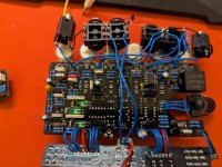
- Space 3pdt engages the internal LED 1&2 which pulse along Rate control (the 2 LEDs which are inside a "fence" made of film caps),
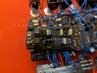
- Time 3pdt turns the internal LED 3 on but this one doesnt pulse at all (bottom left corner of main PCB). Neither bias nor regen trimpots do any difference. I tried to follow the biasing instructions from build docs but having no LFO on any BDD trim setting not much I can do.
- The LED on the BBD sub board lights up and pulses with varying speed depending on Manual, Rate and Depth.

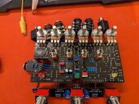
My guess is the LED3 on the main board should also pulse following rate but cannot see or measure anything obvious that could stop it from working. I am adding few pics of the build and schematics from Aion's build docs (pages 21-23).

For reference below a link to a build of another forum member that works perfectly, there's also few photos of internals and a short demo.


Attachments

  • PXL_20231120_160350543.jpg
    PXL_20231120_160350543.jpg
    387.8 KB · Views: 43
  • PXL_20231120_160419368.jpg
    PXL_20231120_160419368.jpg
    378 KB · Views: 42
  • PXL_20231120_160434165.jpg
    PXL_20231120_160434165.jpg
    462.9 KB · Views: 36
  • PXL_20231120_160516082.jpg
    PXL_20231120_160516082.jpg
    421.5 KB · Views: 43
  • xenotron_documentation Noname flange.pdf
    1.1 MB · Views: 6
Last edited:
Solution
I needed to take a break from this one and built the Ring Stinger which was another intimidating Aion board that was waiting it's turn. Turned out perfect, no issues whatsover :) Freakish yet very musical pedal.

I plan to come back to the flanger once I get correct clear LED for BBD board - after some checking I am sure the ultrabright one I used is way out of spec for this place. The recommended one has brightness around 80mcd while the one I used is I think 10000+mcd... :) which surely affects my issues with Manual control and better bbd biasing. I just cant find anything locally like the transparent green LED Aion recommends so until I get the correct one this project fix is on hold. To be continued!
Short update - I swapped...
I had the same solid LED connected to the LDR (have a DeadEndFX board though). I'm not 100% sure what fixed it, but look at the panel LED polarity. I seem to think I had to switch directions? I'll have to go back to my bench and look.
 
Comparing my pedal, LED 3 does not blink. If LED 4 is blinking, then that suggests that the 3201 IC functions. Can you measure the voltages on 3207 IC?

Here are my voltages for the 3207:
1: 0
2: 2.8-3.20
3: 3.18-3.3
4: 6.17-6.59
5: 6.59-7.05
6: 2.9-3.28
7: 4.08-4.23
8: 4.14-4.3
Glad to know the LED3 is working as it should. At the same time it seems the issue is elsewhere - and reflowing everything on the board including sub board and 3PDT boards did not help.

In my example voltages seem more or less in the ballpark - I think they are affected by some settings like depth and manual so wont get same but here we go:

1: 0V
2: 1.95V - 3.2V
3: 2.72V - 2.86V
4. 5.96V - 6.26V
5. 6.49V - 6.7V
6. 2.3V-3V (although with longer measuring at times it starts to go to 3.2-4V range and then back a notch)
7. 2.93V - 3.14V
8. 2.92V - 3.15V

In some cases I might not have caught the exact min / max of the float as my meter is too slow to record everything and the voltage fluctuates quickly.

Setting on my pedal were so the sub board LED4 was blinking intensely, (manual pretty far up, same for depth, rate at mid, input gain maxed out). I was testing and measuring in a dark room with just a PC monitor on and a cloth over the PCB so light should not affect the results here.
 
What I am starting to fear is that the JFet specs make a difference here, or at least some of them do and you can't throw random J113's in and wish for the best. I once built a harmonic trem based on a Catalinbread that didn't work until I started swapping J201s with other JFet transistors - if this one uses any of the J113s for the LFO section I could be screwed
 
According to Aion, reading the manual is a must must must, so ... if everything is checking out, maybe there's an operation wrinkle that was overlooked?
Read it back to back multiple times now, same for Aion build docs - I still take steps back and try to think abt anything I could have done wrong here so just checked all my resistor bags to measure and check whether I don't have something mislabeled - I am not measuring each component before soldering in which can be a potential issue here, any of the hundreds of parts could be faulty. I'll be honest, never had the chance to really go after a troubleshooting like this one so I am enjoying it in a weird way. I will try anything I can to make this work - next on the list is to start desoldering electrolytics and tantalum caps, then transistors and check each for specs
 
That is a lot, dude! And desoldering that many components is a good shortcut to music6000ing/focusing the board. Nobody wants to see a music6000ed board.

aion-crappy-pcb-jpg.60644


Just no.

I think before desoldering, you can at least isolate the section that is giving you trouble via the schematic, since you have some things working, and some not. It seems (impressionistically) like the trouble is located somewhere in the BBD board and interface.

I would at least run a continuity probe along the schematic around the the BBD board ins and outs especially, and then an audio probe in to see what is happening to the signal entering and exiting the BBD area. Audio probes are fun to do, hell, I'd run it from the in jack along the schematic just to see what everything does. Could be the signal is being effected in the BBD, but just not making it out.
 
Last edited:
That is a lot, dude! And desoldering that many components is a good shortcut to music6000ing/focusing the board. Nobody wants to see a music6000ed board.

aion-crappy-pcb-jpg.60644


Just no.

I think before desoldering, you can at least isolate the section that is giving you trouble via the schematic, since you have some things working, and some not. It seems (impressionistically) like the trouble is located somewhere in the BBD board and interface.

I would at least run a continuity probe along the schematic around the the BBD board ins and outs especially, and then an audio probe in to see what is happening to the signal entering and exiting the BBD area. Audio probes are fun to do, hell, I'd run it from the in jack along the schematic just to see what everything does. Could be the signal is being effected in the BBD, but just not making it out.
No worries I don't plan to go full dissasembly mode XD I was placing them with enough care that I am 99.9999% sure I have all the right values in correct places including polarity / orientation etc. I never played much with audio probing but I guess it's time to wrap a cap on a jack and start checking around :) I'll make it work one day and keep it someplace visible as a constant reminder how rough it gets at times
 
I think @comradehoser is correct; it is time to break out the audio probe. I think I would start at C38 and work backwards towards the 3207 IC. You might also want to check the voltages on your transistors prior to audio probing. If one transistor seems off, then you could focus the probe around that transistor. If you need any voltages to compare, let me know. Some of them might be hard to get, but I can give it a try.
 
I checked that many, many times hoping I switched them around :) they are in right places - unfortunately :) I'll do the probing once I get little more time with it and see if I can find anything obvious
Ooh. That's starting to ring a bell with my build. There was weirdness around the MN3207 and no sound getting through. Look around that MN3207/daughterboard run area - it gave me fits. Check chip direction, cap direction, and even values. Even look at the diodes and FET/transistor direction - you might have overlooked something!
 
Ooh. That's starting to ring a bell with my build. There was weirdness around the MN3207 and no sound getting through. Look around that MN3207/daughterboard run area - it gave me fits. Check chip direction, cap direction, and even values. Even look at the diodes and FET/transistor direction - you might have overlooked something!
Self reply:

Did you bias the BBD? You might need to check that. I remember it was a really narrow range when it wanted to work correctly
 
Self reply:

Did you bias the BBD? You might need to check that. I remember it was a really narrow range when it wanted to work correctly
I can't bias it unfortunately - not in a normal way at least with signal coming through main input jack. No matter the trimpot positions there is no modulation appearing. I checked chip positions, transistor orientation, diodes etc - only thing I haven't checked yet are the resistor values.

After probing around the board the only place I am hearing flanging is, weirdly, the loop on MN3102 with LED / LDR4 and C31 100pf cap. There's strong flanging (quiet in volume but deep in terms of modulation sweep) which I can dial in with the BBD bias trim and which responds to regen trim as well. Also worth to mention this all starts to work only with Manual cranked almost all the way. Any Manual pot setting below 3/4 of the way gives nothing around the board other than input signal coming through. This all unfortunately tells me nothing at all, I desoldered the C31 to double check that it's good and it is.

Plugging signal into the BBD chip through Pin3 gives just some quiet output, no modulation - and this works only when I have Manual cranked far up.

I guess I need to backtrack from LED4 through Q15 / Q16 and surrounding resistors to check everything there
 
As a quick update - and kind of a journal for myself - checked all resistor values around, everything is good. I desoldered and double checked all transistors with a component tester, all checked out to be fine as well.
 
Back
Top Bottom