SOLVED Aion FX Xenotron help. (Pictures added)

Anthonyj

Member
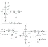
So, for my third build (second being a seabed delay) I decided to do something stupid and build this. After finishing the build, the vibrato (space) seems to work fine. but the modulation s(time) section doesn't want to do anything). also noticed that the loop doesn't work. I think I Did something backwards.

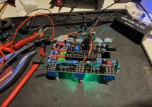
When I plug the pedal in with nothing on LED 2 is fully lit and LED 4 is blinking the rate changes with the knobs.
With space turned on LED 1 Turns on and pulses, LED 2 starts to pulse, and LED 4 is still blinking.
With Time tuned on LED 3 turns on and LED 4 stops blinking.

Any help would be awesome since I got way over my head on this one lol.
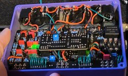
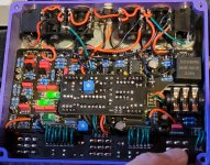
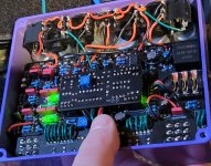
 

Attachments

  • 20231229_095944_resized.jpg
    20231229_095944_resized.jpg
    736 KB · Views: 31
  • 20231229_100007_resized.jpg
    20231229_100007_resized.jpg
    316.3 KB · Views: 31
  • 20231229_100149_resized.jpg
    20231229_100149_resized.jpg
    321.4 KB · Views: 27
  • 20231229_100203_resized.jpg
    20231229_100203_resized.jpg
    479.1 KB · Views: 27
  • 20231229_100212_resized.jpg
    20231229_100212_resized.jpg
    517.4 KB · Views: 32
Last edited:
This issue sounds similar to another thread. The LED for the ultra bright LED 4 (I think) was not spec’ed correct. See this thread.

 
This issue sounds similar to another thread. The LED for the ultra bright LED 4 (I think) was not spec’ed correct. See this thread.


I sourced the exact LED that was specified in the build documents from Mouser the clear green one. It does seem to pulse correctly and respond to the controls but only when then the circuit is off..... When I turn it on the LED becomes solid no longer pulsing.
 
I was testing the case and on. I would describe kinda of the same issue you were noting, there is some vague flanging and self ocilation at almost full cw settings.

The biggest thing that's getting me is the led on the daughter board, when the time section is off the led seems to be the perfect brightness and is properly pulsing with the knob settings. When the time section is engaged It's like the led is getting more voltage and now is brighter and not really pulsing unless I go to extream settings.
 
Hello, welcome.

Quite a challenge for a third project.

I had similar issues with Loop and Time at first. I reflowed some connector pads on the BBD pcb and on the main board, I also realized that some of my transistors were mixed up. I went too fast...
There are one BC559, many BC549 and a few J113. Can you make sure you didn't make any mistake there ?

If all transistors are ok, you can also make sure the v3207 and v3102 are fine. If you have another modulation stompbox using these BBD ICs, you can swap them and check if they're all right.

If you noticed something wrong with Led 4, i'd suggest to perform some continuity tests in the aera, following schematics. Look for shorts and weak or bad connections, reflow carefully everything that seems even slightly suspicious.

I hope you measured every resistors before soldering them ?

20231229_100149_resized - Copie - Copie.jpg

Red circle : I'm sure it's probably nothing, but this thing between these two pads, isn't it a bit suspicious ?

This picture is unfortunately slightly out of focus, but i'd say most of the connector pads looks all right, except those in the bottom right corner of the BBD daughterboard, near the test pads ?

...I would also add some solder on every 3PDT pads, and isolate every jacks sides with some plastic tape : there are some terminals on each jack's sides, they are very close to each other, you may have a short there (blue arrows).

Finally, i circled in green some jack lugs that could be shorting with the back of the enclosure. On my build, i had to flatten these lugs with pliers. Consequently, the sides terminals were also protruding a bit. I pushed them back, and added some tape.
 
Last edited:
Yeah, I would start with a continuity test in through and out of the bbd circuit (see schem).

Actually, before doing that, try the pedal with lid on and the knobs as such: manual 12:00, depth 3:00, LFO 9ish, reaction at 10:00, action 10:00, gain at 3:00. All toggles down.

You can do anything, really, just as long as the action/reaction knobs aren't around 12:00, which effectively does no BBd effect

If you get nothing, you can audio probe in through and out of the BBd schematic to see if you have effected signal and what's happening to it.

I'm assuming that everything is specced per the bom and installed correctly (no funky LDRs and such)
 
Last edited:
Just hit a breakthrough, I was going through @Kris100 Thread and came across his post where he jumped the time tip into the space/ mono out tip. I did that exact change and boom we have modulation. I just need to re bias since I was randomly moving around to try and fix it.

Also one of my led issues mau have been related to using the pre built bezels from love my swithces. I relaized they had a resistor in line and changed them out for some spare Christmas lights I had lying around which made led 4 pulse normally. They are insanely bright though.

I did check all of the transistors they were in the right spots, I added electrical tape between the jacks and across them. I didn't check all of the parts..... so that still could be a shame on me.

So the problem seems to be the flow to the stereo/mono mix? I am trying to read the schematic but that part is a bit confusing across 3 pages.
 
Do you have the switch engaged for stereo? That cuts the signals and indeed you wouldn't get the modulation and tremolo out of the primary outs. So if you don't have the stereo switch or ring lift switch up, but the signals are cut, that could indicate a wiring or switch issue where the switch path is inadvertently activated for stereo.

Could probe (continuity and/or audio) around the right hand side of the first page of the schematic where the modulated signal exits the bbd board and does it's shenanigans with the outs. If you have modulation that is making it to the outs, that is where the switching/mixing happens.
 
Last edited:
I might give the probe a try, just have to make one. But shenanigans is right, reading the schematic makes it seem the transformer only plays a part when the time signal is separated into its own out. I don't see where it mixes back in to the space unless I'm following it backwards around the stereo/mono switch.
 
Audio probe is very simple to make and very fun and instructional to use. You can follow the signal out of modulation and see what happens to it in the outs blocks. The good thing with this circuit is that you don't even need an input signal. It will happily give you super loud disco/electronic beats all day long.

The schematic labeling is a bit ambiguous, but the time ring looks like it may be where the modulated signal connects to the mono space out block. I really don't get the mono/stereo and time switch arrangement at all, though.
 
Last edited:
I need to put this on hold for a few days as I melted some of the jacks when i started to de solder everything. Talking to Lace sensor he thinks I just screwed up wiring the swtich jack since I had a signal when I jumped the time tip to the space tip which makes sense based on my rats nest.
 
They are insanely bright though.
Admittedly I am not that experienced with LDR/LED optocouplers, but when I have built them, I wrap them in heat shrink tubing to keep stray light off of the LDR. Is is possible that the LDRs are reacting to the other LEDs? With 4 of them inside that enclosure, I would think it would light up like a Christmas tree. Again, I don't really know what I'm talking about here, but just a random thought...
 
Just to catch up.
Using the mono/Space out Produces little to NO modulation.
Using the Time Out /Stereo jack works and produces modulation.
If I Jump the Time Tip and combine it with the Space Tip it works and produces modulation.

So, based on what I can tell the issues is however the time signal is mixed back into the mono signal.

I've built the audio probe out of a spare cable and I it is helping immensely. I can't figure out if this is the right direction the signal goes from the Time ring to the time ring switch then it gets mixed back into the mono? Testing in that direction I have modulation all the way up to R26. One side of the resistor modulates the other doesn't, the resistor measures the proper 39K.
 

Attachments

  • TimeExit.JPG
    TimeExit.JPG
    61.3 KB · Views: 9
Last edited:
Well, you should have continuity between the middle lug of the ring lift and the far side of c16/near side of r32. If not, you could always try jumpering from c16 or r32 to see if you get audible modulation. Just remember to put action/reaction knobs off of noon (9 or 3, don't matter), and turn up depth and manual to at least noon.

It might be more profitable to do an audio probe working forwards from the BBD board so then you can see what, if anything, is happening to the modulated signal and where it drops out.

I had a moment of clarity after reading the manual. The mono-stereo switch only applies to rectify phase of the signal when it the delay/modulation is *bypassed* in mono or stereo operations. Otherwise, the modulated signal travels to the time out jack and then to the space out jack if nothing is inserted into the time switch-jack. I am inferring that this happens via the ring switch since the ring switch solder point proceeds from the time out ring switch, and is right next to the space out solder point on the board. The schematic also indicates that "time ring switch" at r26 feeds into to the space out.

So, if I understand this correctly, the modulated signal should be coming in via "ring" on the right of the jack, which is connected to "ring switch" on the left of the jack, which is connected to the space out. When you push the cable into the time out jack, it lifts the tang connecting the ring (right side) to the ring switch (left side) breaking that circuit, at the same time you get the modulated signal fed through the transformer to the tip and sleeve when the cable is inserted, no doubt to give enough juice to the stereo signal or make it proper in some way. The ring conspicuously is not connected through the transformer. So you could probe continuity/audio in the time out ring, ring switch, and associated parts. Might be a bad solder point/reflow candidate at the "ring switch" board-in or at the ring switch itself.
 
So that's what I did and I was able to track modulation all the way up to R26. On the other side of R26 there was no longer modulation. So even though the resistor reads correctly could it still be bad? I did do a reflow on it but didn't replace it.
 
So that's what I did and I was able to track modulation all the way up to R26. On the other side of R26 there was no longer modulation. So even though the resistor reads correctly could it still be bad? I did do a reflow on it but didn't replace it.
It's possible, but you may also want to look for shorts around R26. You may also want to double check the value or R26. It's supposed to be 39K. I can't exactly tell from the picture, but a 39K 5 band resistor should read, Orange, White, Black, Red, Brown. That 4th band looks violet, which would make it 3.9G.
 
If you have continuity on either side, then it's the most likely the component. If you have no continuity on one side, then probably a damaged trace or pad. You can jumper over the resistor, too and see what happens.
 
The R26 was the proper 39k but I felt wierd about the resistor slot itself so I replaced it with a new one. There was no difference but jumping the resistor is making it work correctly. I'm not really sure what the issue but it seems to be with that slot. At the point I don't even know if I want to pursue it any harder for fear I'll just break the damn thing.

It was a good experience though since I got to learn better schematic reading and built and used the audio probe.

Here is a picture of what it ended up looking like as I removed the sockets and running test after test.

Also as a side note if your testing a board with a daughter board make sure you put it back on if you remove it, can't tell you how many times I did this and thought it got worse cause there was no mod at all any more lol.
 

Attachments

  • 20240104_214441.jpg
    20240104_214441.jpg
    877.1 KB · Views: 9
Back
Top