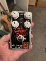
Anyone have experience with repairing pedals?

jwyles90

Well-known member
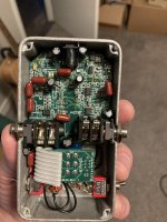
I found this at a pawn shop for $15 the other day. They told me that it didn't work, so I figured the worst-case scenario was I take a $15 crash course in messing it up further, best case I fix it and get a working pedal for cheap. It turns on, but no sound other than a high-pitched whine comes through when engaged.

This might sound like kind of a silly question since we all do troubleshooting in one way or another with our own builds. But I'm curious if anyone has any experience or tips for repairing already broken pedals? I figure taking an audio probe to it is a good place to start, and looking for anything that visibly jumps out as damaged. Outside of that, I'd be curious to hear if anyone has had any success repairing pedals elsewhere. I also recognize that SMD repairs could be a totally different kind of beast than through-hole.
IMG-9529.JPG
IMG-9530.JPG
 
First thing I'd do is locate the protection diode and check if it's dead. Number one killer of pedals is people plugging in the wrong power supply.
That was my thought as well. Looks like it might be up in the top left corner. I haven't had much time to really sit down and check individual components yet but that'll be the first thing I do!
 
That was my thought as well. Looks like it might be up in the top left corner. I haven't had much time to really sit down and check individual components yet but that'll be the first thing I do!
Soul Food is a Klone, I believe. Not sure how easy it'd be to locate a schematic, but I think you might be able to compare it to known Klones. I fixed an EHX pedal that had a broken switch, which I replaced, so I know that it's possible to fix them.
 
I've done repairs, but I don't enjoy it so I don't do it unless I have to. But I approach it the same way I do a general debug:
  1. Visual inspection - does anything look wrong/fried/damaged/missing?
  2. Continuity inspection - does the 3PDT operate the way it's supposed to? Do the pins connect when they should? Do the jacks have continuity to the switch and from the switch to the main PCB?
  3. Voltage inspection - do I get the right voltages where I'm expecting them? 9V at input, 9V into charge pump, +18/-9 out of charge pump, check voltage rails on all opamps
  4. Audio probe - at what point does the signal stop getting through? What components would be preventing it from going further?
You don't always need all 4 steps, and obviously there are sub-steps that can come up during these steps, but often you'll find the problem by step 2 or 3 (or step 1 if you're lucky).
 
Just off the bat, I would check the soldering on D2&3, probably just clippers, but may as well eliminate if possible. Also, D5 looks a little melty and maybe the IC next to it too. Just my brief visual observations
 
I've done repairs, but I don't enjoy it so I don't do it unless I have to. But I approach it the same way I do a general debug:
  1. Visual inspection - does anything look wrong/fried/damaged/missing?
  2. Continuity inspection - does the 3PDT operate the way it's supposed to? Do the pins connect when they should? Do the jacks have continuity to the switch and from the switch to the main PCB?
  3. Voltage inspection - do I get the right voltages where I'm expecting them? 9V at input, 9V into charge pump, +18/-9 out of charge pump, check voltage rails on all opamps
  4. Audio probe - at what point does the signal stop getting through? What components would be preventing it from going further?
You don't always need all 4 steps, and obviously there are sub-steps that can come up during these steps, but often you'll find the problem by step 2 or 3 (or step 1 if you're lucky).
Agreed. You should probably pull the guts out of the enclosure so you can closely inspect everything first.

Good luck! I hate trying to sort out other people’s mods almost as much as I hate trying to fix pedals.
 
Is D5 okay? Are the right pads of D2 and D3 soldered?
Just off the bat, I would check the soldering on D2&3, probably just clippers, but may as well eliminate if possible. Also, D5 looks a little melty and maybe the IC next to it too. Just my brief visual observations
Yea the picture makes it look worse than it is but that's all just flux I believe. D2 & 3 are definitely a little wonky looking, so I'll try reflowing those as well.
 
Agreed. You should probably pull the guts out of the enclosure so you can closely inspect everything first.

Good luck! I hate trying to sort out other people’s mods almost as much as I hate trying to fix pedals.
Yea when I've got a little more time to sit down with it I'll take it all out. I'm willing to bet someone used the wrong kind of power supply and fried the diode, since I can't imagine JHS would put out a modded pedal that was messed up in some other kind of way. But maybe I'm giving them too much credit.
 
Yea when I've got a little more time to sit down with it I'll take it all out. I'm willing to bet someone used the wrong kind of power supply and fried the diode, since I can't imagine JHS would put out a modded pedal that was messed up in some other kind of way. But maybe I'm giving them too much credit.
The clipping mod has a useless diode.
 
D2 & D3 are where the stock Diodes go, JHS has removed them & wired from there to the toggle switch.
Stock I think these used silicon & modders were were swapping them out for germanium or both???
I would have a wild guess & say somebody plugged the wrong power supply in & fried the polarity diode???
 
Interesting. Would that prevent the pedal from working altogether?
No, it’s just unnecessary. They have three diodes in parallel. To have asymmetric clipping, two have to be in series with the same orientation (e.g., AK-AK) with one anti-parallel (e.g., KA). They currently have symmetrical clipping with a bonus diode hanging out. Diodes in parallel can be used for increasing current carrying capacity, but that’s not relevant here.
 
D2 & D3 are where the stock Diodes go, JHS has removed them & wired from there to the toggle switch.
Stock I think these used silicon & modders were were swapping them out for germanium or both???
I would have a wild guess & say somebody plugged the wrong power supply in & fried the polarity diode???
I had a Soul Food. Stock clippers were bat41
 
I've done repairs, but I don't enjoy it so I don't do it unless I have to. But I approach it the same way I do a general debug:
  1. Visual inspection - does anything look wrong/fried/damaged/missing?
  2. Continuity inspection - does the 3PDT operate the way it's supposed to? Do the pins connect when they should? Do the jacks have continuity to the switch and from the switch to the main PCB?
  3. Voltage inspection - do I get the right voltages where I'm expecting them? 9V at input, 9V into charge pump, +18/-9 out of charge pump, check voltage rails on all opamps
  4. Audio probe - at what point does the signal stop getting through? What components would be preventing it from going further?
You don't always need all 4 steps, and obviously there are sub-steps that can come up during these steps, but often you'll find the problem by step 2 or 3 (or step 1 if you're lucky).
I'd add Step "0." to this list - the sniff test - gives you an idea if something might have burnt out.
 
Back
Top