
jhaneyzz
Well-known member
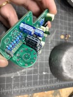
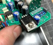
Assembling a MadBean Archibald and trying to decipher the instructions.
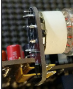
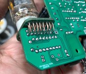
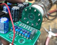
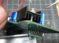
If I solder the tube board to the header pins on the “solder side” it seems to me the tube will end up on the “btm” of the tube board rather than the “top”
I can’t seem to find any gut shots showing the proper orientation.
If I solder the tube board to the header pins on the “solder side” it seems to me the tube will end up on the “btm” of the tube board rather than the “top”
I can’t seem to find any gut shots showing the proper orientation.


 Are you planning on drilling any holes in the enclosure for heat dissipation?
