Cephoid CE-2 - Trimmer Tuning Setting

equinox

Member
Hey guys

I figured I'd just post a thread to cover this one topic on tuning the Chorus pedal.
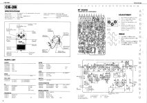
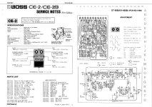
Attached are the Service Notes form BOSS for the CE-2 and CE-2B!
It shows the potentiometer settings and how to set the signwave.
It shows an 200Hz signal on the input, but +3dBm of amplitude?!?
I have a handheld audio signal generator unit and can select the frequency, but there is a trimmer on it to set the voltage, but nothing in regard to dbm!
So my question is...what VOLTAGE to set the unit at? As I can put the O-scope on it and adjust to an RMS voltage amplitude...if known.

What is the calculation if there is one for dbm to Voltage?? Is this chart in the link accurate?? It as well as others I Googled and did my due dilligence had calculations, but asked for information I did not know, such as in this one...it'll calculate Volts rms to dBm...I could plug voltages, but is asking for OHMS!! I have no idea what this is (as others)!!

This chart is suggesting +3dbm is equal to 315.853V rms.

PLEASE CONFIRM.

https://www.engineersedge.com/instrumentation/Volts_to_dBm.htm
BOSS CE-2 Service Notes_Page_1.jpg BOSS CE-2 Service Notes_Page_2.jpg
 
Last edited:
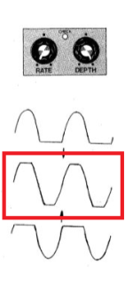
The amplitude of the input wave is not super critical. Somewhere between 0.5-2V p-p would be fine. If you look at Figure 2 in the CE-2B service manual, this is what you typically observe on your scope when you are measuring the output of your BBD and adjusting the bias voltage trim. The inputted sin wave is chopped either at the top or the bottom depending on where your bias is set. If your inputed signal is too small then you would only see the chopping at the extremes of the trim turn and a clean signal the rest of the time. While biasing you are trying to get the trim set so the input wave is right in the middle of chopping on both sides. If your input wave is too large you will see chopping on both top and bottom of the wave, this is actually a best case scenario as long as it's not too extreme. You can very precisely find the middle balancing the amount of chop on both sides. I also usually try a few other frequencies and sometimes get a better image on the scope, but remember, depending on the circuit they might be filtered out.

Anyway, that is my general procedure for setting the bias on most BBD circuits. Now for the bad news: the CE-2 has a weird circuit design, in that the bias trim also sets the reference voltage for the op-amps (usually set by a voltage divider to 1/2 of the input voltage (4.5V). This was likely done to save a few parts. Because of this, I have never had much luck setting these up with the scope, but you should defiantly give it a try. If it doesn't work the best way to set it up is to have a guitar signal looped into the input of the pedal, set the trim to one extreme and slowly turn it until you start to hear chorusing. Mark that position on the trim with a sharpie. Repeat this with the other trim extreme. Now set the trim in the middle of your two marks.
 
Last edited:
thanks for your guys' input.

Yes, you want to be in the middle clipping equally as show in the service notes (see below). If the input signal is too low, you probably will not get them to clip and if too high, they will be clipping all the time, so can't dicypher and balance out, so amplitude would be key. Not sure why they chose 200Hz, but it was obviously for a reason, so will be selecting that frequency.

I've been in engineering for almost 30 years, I get what the service notes are depicting and I don't like approximations, like "in the middle of the two extremes" nor "by ear". I go by hard data.

BOSS outlines how to tune their product and if one did that, would by theory be spot-on every time and consistent!

Therefore, I'd like to adhere to it and just need to know the correlation between dbm and voltage and if the table I found and 315.853V rms is correct, or not, and if not, what should it be? Just need confirmation, but it does seem correct in the fact, if memory serves me...I was getting in the hundred of mV output from my guitar pickups when I measured previously.
 

Attachments

  • Balance.png
    Balance.png
    30 KB · Views: 2
Last edited:
i'm a manager, engineer, and sr. tech by trade. I don't like approximations, like "in the middle of the two extremes" nor "by ear". I go by hard data.

BOSS outlines how to tune their product and if one did that, would by theory be spot-on every time and consistent!
therefore, I'd like to adhere to it and just need to know the correlation between dbm and voltage and if the table I found and 315.853V rms is correct, or not, and if not, what should it be? Just need confirmation, but it does seem correct in the fact, if memory serves me...I was getting in the hundred of mV output from my guitar pickups when I measured previously.
There was some really great information and advice given by some very experienced and well respected builders, one of which is an engineer. I'm going to give my two cents, but I'm not sure why because I already know how it's going to be taken, or disregarded based on prior responses.

Boss had production lines set up for building and testing of circuits, they likely picked the method of calibration that was the fastest and easiest for consistency. 200-300hz is in many of the old boss service manuals and is common in many vintage effects of the time, likely as it falls within range of the average guitar signal of the time. I'm not an EE and circuit designer for boss so don't quote me on that. Speaking of EEs, you aren't going to find that many here as this is a hobby forum.

While we are talking about it, the test equipment used many people don't own. I've built hundreds of pedals over the years, many of which are BBD pedals, just like this, which I have built around 6 or 7 of. I have calibrated by ear, or by scope. By ear is totally fine and will yield excellent results. By scope, I injected a 200hz sine wave and calibrated for a perfectly symmetrical wave with no clipping on either end of the wave. I don't own a fancy and expensive signal generator so I'm using an app based generator on my phone so I can only hit 0db on the volume. Again, we are hobbyist building primarily for ourselves and spending hundreds on a signal generator isn't likely around here. The replies above were very informative and helpful but they weren't as exact as you want because you're that person.

My advice would be to remember that this is a hobby forum and not full of engineers with laboratories full of expensive test equipment and degrees in EE. I would also be inclined to think that someone with that knowledge and equipment would be capable of equating the answer, or know who to talk to to find the answer. I'm sorry we are of no help here, I hope you find the information you seek but I would ask that you try to keep in mind that we are not arguing with you and also just learning and our knowledge base is from none at all to self taught novice.

When asking for help please be nice and I would encourage you to not spam up every recent build reports with your demands for answers. Good luck with your calibration✌️
 
is it REALLY that hard just to answer my question, which is correlation between dbm and voltage and if the value and link I provided is correct or not?!?? :LOL::ROFLMAO:
dBm is defined as power ratio in decibel (dB) referenced to one milliwatt (mW). It is an abbreviation for dB with respect to 1 mW and the "m" in dBm stands for milliwatt.

Let it go buddy having an aneurysm over a chorus pedal hardly seems worth it.
 
is it REALLY that hard just to answer my question, which is correlation between dbm and voltage and if the value and link I provided is correct or not?!?? :LOL::ROFLMAO:


Is it really that hard to listen to the advice from other members and not spam the same question on other people’s build reports? If you are who you say you are, then you should know that the dBm to v or dBu to v calculation thing is based on load impedance. You want a simple, clear cut answer, how about this? Set the amplitude of your signal to 1.41 ac volts using a basic ass multimeter. Follow the boss service notes. Close enough.
 
Last edited:
Is it really that hard to listen to the advice other members and not spam the same question on other people’s build reports? If you are who you say you are, then you should know that the dBm to v or dBu to v calculation thing is based on load impedance. You want a simple, clear cut answer, how about this? Set the amplitude of your signal to 1.41 ac volts using a basic ass multimeter. Follow the boss service notes. Close enough.
You must not know how to read my guy, he doesn't want close enough, he wants hard and raw data 😂
 
There was some really great information and advice given by some very experienced and well respected builders, one of which is an engineer. I'm going to give my two cents, but I'm not sure why because I already know how it's going to be taken, or disregarded based on prior responses.

Boss had production lines set up for building and testing of circuits, they likely picked the method of calibration that was the fastest and easiest for consistency. 200-300hz is in many of the old boss service manuals and is common in many vintage effects of the time, likely as it falls within range of the average guitar signal of the time. I'm not an EE and circuit designer for boss so don't quote me on that. Speaking of EEs, you aren't going to find that many here as this is a hobby forum.

While we are talking about it, the test equipment used many people don't own. I've built hundreds of pedals over the years, many of which are BBD pedals, just like this, which I have built around 6 or 7 of. I have calibrated by ear, or by scope. By ear is totally fine and will yield excellent results. By scope, I injected a 200hz sine wave and calibrated for a perfectly symmetrical wave with no clipping on either end of the wave. I don't own a fancy and expensive signal generator so I'm using an app based generator on my phone so I can only hit 0db on the volume. Again, we are hobbyist building primarily for ourselves and spending hundreds on a signal generator isn't likely around here. The replies above were very informative and helpful but they weren't as exact as you want because you're that person.

My advice would be to remember that this is a hobby forum and not full of engineers with laboratories full of expensive test equipment and degrees in EE. I would also be inclined to think that someone with that knowledge and equipment would be capable of equating the answer, or know who to talk to to find the answer. I'm sorry we are of no help here, I hope you find the information you seek but I would ask that you try to keep in mind that we are not arguing with you and also just learning and our knowledge base is from none at all to self taught novice.

When asking for help please be nice and I would encourage you to not spam up every recent build reports with your demands for answers. Good luck with your calibration✌️
Thanks. Yes, I wasn't thinking of the audience as all I work with for the past 28 years and not mom-and-pop companies, but $40-50B top 10 companies are engineers and management all day and exact answers are demanded and all I was asking for to fill in the blank of +3dbm = x.xxxmV! Very simple....

As far as engineers....there are mechanical, electrical, software, chemical...Joe Blow may think...well, an "engineer" should know.
But an engineer in one field doesn't mean expert in another...likewise a EE in Body Control Modules is not an expert in Smart Junction Boxes, so remember that. It's not like....so-and-so is an engineer, so they should know everything "engineering"! lol Thinking that an avenue, such as a forum, that does include real engineers would be available and easily answer a question is a smart move in my book. As someone once told me in my career and in college....it's not always in knowing the answer....but knowing how to obtain it that is intelligent!

I would likewise advise people to watch how they comment. Some of the replies by members could be conceived as bullying and hostile and could get people kicked off of forum(s). If you don't have the answer to someone's question....MOVE ON! It's not really that hard....really!

As you said...BOSS came up with a quick method to tune the circuit for production. I found the actual Service Manual and supplied it was thanked by members for that. I'm just looking to close the loop on exactly what equipment would be needed and how to do it, as the Service Note is not exactly complete. The intention would be to HELP others.

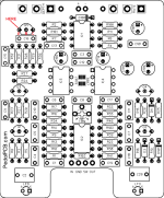
There is a difference in component enumeration between the BOSS schematic and PedalPCB schematic. The emitter of Q3 for the novices that do chime into this thread, is Q5 on the PedalPCB board and identified in the attached photo.
 

Attachments

  • Pin.png
    Pin.png
    280.1 KB · Views: 3
Thanks. Yes, I wasn't thinking of the audience as all I work with for the past 28 years and not mom-and-pop companies, but $40-50B top 10 companies are engineers and management all day and exact answers are demanded and all I was asking for to fill in the blank of +3dbm = x.xxxmV! Very simple....

As far as engineers....there are mechanical, electrical, software, chemical...Joe Blow may think...well, an "engineer" should know.
But an engineer in one field doesn't mean expert in another...likewise a EE in Body Control Modules is not an expert in Smart Junction Boxes, so remember that. It's not like....so-and-so is an engineer, so they should know everything "engineering"! lol Thinking that an avenue, such as a forum, that does include real engineers would be available and easily answer a question is a smart move in my book. As someone once told me in my career and in college....it's not always in knowing the answer....but knowing how to obtain it that is intelligent!

I would likewise advise people to watch how they comment. Some of the replies by members could be conceived as bullying and hostile and could get people kicked off of forum(s). If you don't have the answer to someone's question....MOVE ON! It's not really that hard....really!

As you said...BOSS came up with a quick method to tune the circuit for production. I found the actual Service Manual and supplied it was thanked by members for that. I'm just looking to close the loop on exactly what equipment would be needed and how to do it, as the Service Note is not exactly complete. The intention would be to HELP others.

There is a difference in component enumeration between the BOSS schematic and PedalPCB schematic. The emitter of Q3 for the novices that do chime into this thread, is Q5 on the PedalPCB board and identified in the attached photo.
JFC... You did the same shit when you posted a thread about your XC phaser and you're putting way too much stock into this. You have been given sound advice more than once yet, you continue to argue. We're talking about guitar effects. The important thing is about how they sound and not about how they they look visually on an oscilloscope. Bias the damn thing to where it sounds the best. End of story.

Edit: As I mentioned earlier, dBm to v is based on impedance. Industry standard for telephone/audio applications is 600 ohms. I assume that’s the standard boss/Roland used. 0 dBm is .78v RMS. 3 dBm is pretty much 1.1v RMS. 5 dBm is around 1.41v and 10 dBm is 2.5v. Don’t believe me? Use the calculator you linked earlier with 600 as the value for Zo and the voltages I listed for V1.
 
Last edited:
In my experience with building several different chorus circuits, and including repairing several of the various Boss chorus units, the tweaking can be done by ear with a simple guitar input. What's important is that the trimpot for adjusting the chorus effect is done in VERY TINY increments, as the "sweet spot" is in a very narrow sweep range of that trimmer. I usually start with that trimmer centered then go very slowly to the left (CCW). If that doesn't get it, I go back to center and very slowly go to the right (CW). That will usually get it. Using a signal generator, scope or other test gear is not really necessary.
 
Back
Top