Hi all! First off, this is my personal build and not a PPCB project. If that is not allowed here let me know!
I am really stumped on this one. I designed my own layout and circuit board and it has been assembled with SMD components by JLC so I am confident that the component values are correct.
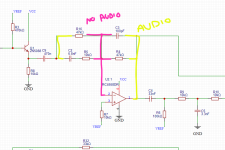
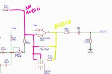
The audio passes fine though the top un-modulated section of the circuit. I audio traced the signal through the modulation section to the input (pin 3) of the V3207. It dies there. Nothing on the output pins 7 and 8. If I remove the V3207 and jumper from pin 3 to 7/8 the rest of the circuit works. So there is an issue with the BBD/clock/LFO section. I have swapped in a working V3207 pulled from a working chorus pedal so I know it's not the BBD as well. Also, I bought an oscilloscope to test the LFO and I get a nice triangle wave from the depth pot of the LFO and a modulated wave form on pin 7 of the clock when I adjust the rate and depth controls. I have checked my schematic at least 30 times, I can't see anything off from the CE-2 other than my vibrato/tone and master level mods which shouldn't affect the modulation section. All voltages seem good. Both VREF is around half supply voltage.
Thanks for any ideas to check!
My schematic attached.
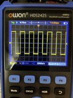
Clip of wave form from pin 7 of the clock:
Pic is of wave form on pin 2 and 6 of the V3207 from the clock (attached second pic).
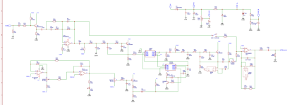
Stock CE-2 schematic for reference:
I am really stumped on this one. I designed my own layout and circuit board and it has been assembled with SMD components by JLC so I am confident that the component values are correct.
The audio passes fine though the top un-modulated section of the circuit. I audio traced the signal through the modulation section to the input (pin 3) of the V3207. It dies there. Nothing on the output pins 7 and 8. If I remove the V3207 and jumper from pin 3 to 7/8 the rest of the circuit works. So there is an issue with the BBD/clock/LFO section. I have swapped in a working V3207 pulled from a working chorus pedal so I know it's not the BBD as well. Also, I bought an oscilloscope to test the LFO and I get a nice triangle wave from the depth pot of the LFO and a modulated wave form on pin 7 of the clock when I adjust the rate and depth controls. I have checked my schematic at least 30 times, I can't see anything off from the CE-2 other than my vibrato/tone and master level mods which shouldn't affect the modulation section. All voltages seem good. Both VREF is around half supply voltage.
Thanks for any ideas to check!
My schematic attached.
Clip of wave form from pin 7 of the clock:
Pic is of wave form on pin 2 and 6 of the V3207 from the clock (attached second pic).
Stock CE-2 schematic for reference:
Attachments
Last edited: