Custom Range Potentiometers

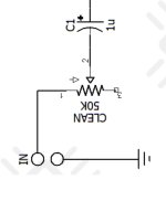
I’m new to this and wondering if there is a such thing as a custom-range potentiometer. For example, if I bought a B100k and wanted to configure it so that at the bottom of the range it started at 12k resistance and at the top of the range it landed on 88k resistance.

My uneducated guess would be that I’d need to add a resistor or trim pot on both sides of it to define its range. For example, a trim pot on both sides hidden from the user but adjustable at the circuit board could let me configure it on the fly to try different ranges. Am I close or way off?
 
Adding trimpots or select-in-test resistors at each end is a good way to control the range, and to some extent the taper, of a pot.

Do you want the pot to act as a voltage divider (3 terminals) or as a variable resistor (2 terminals)?

What matters most with a 3-terminal pot is the ratio of resistances, rather than the absolute resistance.

With a 2-terminal pot, the only things that matter are min resistance, max resistance & taper.
Voltage divider vs variable resistor? I’m not sure. This is a good question as it will prompt some research on my end. I’m not even sure if I understand the difference yet. I was under the assumption that a typical level, tone, or gain knob on a pedal circuit are 3-pin pots acting as variable resistors. Maybe that is not the case. Or maybe it just depends. (I’ve seen the Walrus Eons fuzz pedal has a voltage knob at the top-center position. Maybe this is an example of a pot being used as a voltage divider. I don’t know.)

The use I was thinking of was for a typical gain, drive, or fuzz-amount knob.
 
  • Like
Reactions: Nic
They could be either type, it depends on the circuit.


This is an example of a pot used as a variable resistor (aka rheostat). Either two lugs are tied together, or one is unused completely.
It acts as a single variable resistance. Turning up the pot increases the resistance, turning down the pot decreases the resistance.
1710505373104.png


These are examples of pots used as voltage dividers. All three lugs are used (and none are tied together).
The signal/voltage on lug 2 is divided up by the ratio of resistance between lugs 1 and 2, and lugs 2 and 3.
1710505384072.png
 
They could be either type, it depends on the circuit.


This is an example of a pot used as a variable resistor (aka rheostat). Either two lugs are tied together, or one is unused completely.
It acts as a single variable resistance. Turning up the pot increases the resistance, turning down the pot decreases the resistance.
Okay, so, in these figures below we have a “clean 50K” trim pot and a “bias 5K” trim pot. Help me clarify or understand something please… is the “clean 50K” pot an example of a variable resistor instance where lug 3 is unused? Also, is the “bias 5K” pot an example of a variable resistor where lug 2 and 3 are “tied together”?
 

Attachments

  • IMG_0374.jpeg
    IMG_0374.jpeg
    51.5 KB · Views: 5
  • IMG_0375.jpeg
    IMG_0375.jpeg
    75.8 KB · Views: 5
That's correct. All three pots (Clean, Bias, and Sundial) in those pictures are variable resistors.

They work exactly the same regardless of whether the unused pin is left open or tied to the center wiper.
 
That's correct. All three pots (Clean, Bias, and Sundial) in those pictures are variable resistors.

They work exactly the same regardless of whether the unused pin is left open or tied to the center wiper.
Okay, interesting. So, I’ve got this circuit where I’m modifying it from internal trim pots to external pots. I’ve got it wired like this (see pic). It may be overkill that I’m wiring all three lugs. Maybe I could get by wiring only two lugs.
 

Attachments

  • IMG_9926.jpeg
    IMG_9926.jpeg
    290.9 KB · Views: 6
Back
Top