DC Power and Its Relationship to AC Signal

talljohnbrown

New member
This is more of a question related to the fundamentals of electrical currents, but I haven't found a direct answer:
  • How does the DC Power interact with the AC signal (guitar pickups, other audio signals, etc) coming into an effect?
I understand the use of DC power as it relates to powering opamps and other ICs, coupling/decoupling caps, and the use of those same caps to prevent DC from getting to the guitar and such. To elaborate on my question through example, if a "flat" 9V is going across the wire, it technically can't be out of phase since it doesn't have a drastic rise and fall in voltage like AC, so is that DC power only used to power components (ICs, LEDs, and the like) or is there something more simple I am missing at a fundamental level? If this question isn't clear, I can happily try and explain myself better, but I think I know what I am asking for but if I need straightened out by all means, school me.
 
My (far from expert) understanding is that AC "rides" on top of DC, similar to the way waves from a stone dropped into a pool of water "ride" on the flat surface of the water.
 
That would make sense. What I should have asked is if AC and DC can coexist on the same conductor since that is ostensibly what is happening, correct? If that is what is occurring in an effect circuit, then it might just be a complex waveform where the sine wave (or whatever wave) is similar to the answer I found here.
 
I am just guessing but I believe this is how rectifiers work.
For example, in Tube Amps you have Line In wall voltage. The rectifier filters out the AC and leaves the DC.

Are you thinking having AC voltage mixed in for a bigger sound? I think AC would blow up an effects circuit by it's 'wild' nature.
 
No, I am just not familiar enough with the flow of electricity inside of a circuit to come to my own conclusion on what is happening so I figured I needed to ask on here to see if anyone can explain it like I'm 5.
 
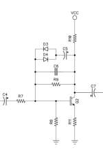
@iamjackslackof is right. Waves can coexist at the same time, but they serve 2 different functions when it comes to pedals. Think of DC as powering up your components and think of AC as your guitar signal. Now, that being said take a look at the below schematic. It is the first clipping stage of a BMP. A general circuit rule for us is that capacitors block DC, but allow AC through. C4 and C7 are coupling caps, meaning that they block DC coming from the previous stage and going to the next stage. They're purpose is to not throw off the voltage/current going to the device in question. If you take a look at R9, you can see that both AC and DC are going through it. R9 and R8 together form a voltage divider to power Q2 base and open it up. R11 sets the gain of the BJT. R10 sets the voltage going to the collector of Q2 and also the amplification of this stage. C6 here tames the highs of your AC signal. The diodes do the clipping here and C5 selects what signals get clipped.

Does this help?

1686576206504.png
 
Yes, this absolutely helps! I figured if they coexisted then they would travel through transistors and other components together before the transformed AC signal was passed on through C7 in this case. thank you all I appreciate it.
 
Let's take a look at the Fender 5E7 tube circuit that Leo Fender came up with a long time ago. You have a center-tap winding pair feeding a 5U4 dual rectifier tube. It has two plates(anodes), a cathode, and a filament. Each anode passes half of the input sine wave. The output D.C. appears on the filament as you can see on the circuit diagram. The filtering is done by the D.C. de-coupling capacitors and the 'choke'(an inductor). The choke is depicted by the curly horizontal squiggle with the two horizontal lines on the top and where it says 415 volts. The 'caps' charge up to a D.C. level and the choke passes D.C. current and resists passing A.C. current. The higher the impressed A.C. frequency, the higher the inductive impedance as offered by the choke. The rectifier tube(this could be a solid state rectifier) does not filter the voltage. It makes D.C. voltage out of A.C. voltage. There is a lot of ripple on this raw D.C. voltage. Without filtering the D.C. waveform looks like a succession of positive A.C. voltage humps, all side-by-side. This is why filtering is required. It smooths out the D.C., almost to a straight line. Also, the more you load the power supply, as in draw more current from it, the more the ripple or hum increases.
 

Attachments

  • Fender_bandmaster_5e7_schem.pdf
    98.5 KB · Views: 6
That would make sense. What I should have asked is if AC and DC can coexist on the same conductor since that is ostensibly what is happening, correct? If that is what is occurring in an effect circuit, then it might just be a complex waveform where the sine wave (or whatever wave) is similar to the answer I found here.
Yep, the first answer pretty much covers it. If your power rails are at 0 and 9 volts and you need maximum headroom for a symmetrical signal you need to offset the AC signal for more or less equal excursion in both directions, hence the nominal 4.5 volt bias that we see so often in pedals.
 
Back
Top