giovanni
Well-known member
I got a Small Stone from a coworker for free. It’s completely dead: no sound and not even the LED turns on. I opened it up today and couldn’t find anything obviously wrong inside. The foot switch seems to work and then components and solder joints look good.
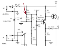
However I noticed that there is DC voltage on the output and on other spots in the circuit so my guess is that there is something wrong with the power section. I haven’t looked at the schematic yet but I wanted to ask for advice on how to proceed. What could be broken? Could a busted LED cause this? I ask because I once burned an LED in a pedal and it stopped working, then I replaced it and it was fine.
Any suggestions are appreciated!