Deflector loses effect after a while

p_wats

Well-known member
Here I am with another FV-1 based troubleshooting thread, alas.

I've got a populated Deflector PCB here that works fine for a while, then the wet signal cuts out---sometimes a quick stop, others an intermittent sputter, but the effect always stops at some point.

The key thing to note here is that I soldered the FV-1 myself (after stealing the chip that had been on this board to try and troubleshoot another build---the less we speak of that the better, for now). This isn't my first time soldering an FV-1 and the joints look good in a magnifier.

It's a brand new chip. I've fluxed and reflowed each pin carefully, which always seems to bring the pedal back to life, but the most I've gotten out of it is about 15 minutes of playing before it sputtered out again.

I assume that points to an intermittent connection with one (or more) of the pins, but I've already fluxed and reflowed the joints so many times (including the rest of the pedal) that I'm curious if there's something else I may want to try.

When it's working it sounds great (though there is a whine during a portion of the Density pot sweep, but I can work on that later).

Anyone ever run into something similar before?
 
I've carefully reflowed the pins of the FV-1 and all other solder joints. Curiously, it seems to start up again if I've simply left it alone for a while (ie, disconnect power and reconnect it a few hours later and it is again fine for a short period).

I'm hoping this is something more to do with power to the chip than the chip itself, but I'm open to suggestions.
 
When it stops, do you still get dry through, or totally silent? Does dry signal get through the fv-1 (like if mix knob is all the way wet, do you get dry sound like the fv-1 is passing it through with no effect, or silent like the fv-1 isn’t passing any signal?

Interestingly, I repaired a friend’s EQD afterneath. Sometimes the effect would cut out but the fv-1 still passed signal, it was just dry. What happened was in EQD’s design, one of the mode selection pins wasnt really tied to ground or 3v3, it was just kinda floating, electrically speaking. Static charge would make it toggle, and when it toggled it changed to different mode which just passed dry. I confirmed this by grounding pin13 and checking what modes it was toggling with the fv-1 datasheet. Tying the offending pin to ground through a 22k resistor permanently solved it.

For the deflector I think pedalpcb just grounded all three mode selection pins (prgm 0), so it shouldn’t have the same static problem that EQD did. Just mentioning since the issue is similar, intermittent effect, so you could check that all those pins have solid continuity to ground.
 
run the pedal to the point where you lose the wet output and leave the pedal powered on. leave an audio signal playing if you can. check the power and ground pins on the FV-1 to make sure each are OK.

use an audio probe to see if your wet signal still appears on pins 27 and 28 after you lose it in the output. if you still have a wet signal there you can troubleshoot the output from there. if you don't have wet signal on 27 and 28 after you lose it in the output, see if you still have dry signal going into pin 2 on the FV-1. I don't think you would have any feedback input on pin 1 if you don't have a wet signal on 27 and 28.

these symptoms might be a capacitor charging slowly that is somehow gating the wet signal. powering the pedal off would likely discharge the capacitor after a bit of time and then it would work again when you restart it, up to the point where the capacitor charges again and stops the signal. that is what I would try to track down if you either lose the dry signal going in to the FV-1, or if the wet signal is present on pins 27 and 28 but not reaching the output. but -- assuming you have the right power and ground -- the problem might be happening inside the fv-1 chip instead of on your board if you have the dry signal going in but no wet signal coming out.
 
When it stops, do you still get dry through, or totally silent? Does dry signal get through the fv-1 (like if mix knob is all the way wet, do you get dry sound like the fv-1 is passing it through with no effect, or silent like the fv-1 isn’t passing any signal?

Interestingly, I repaired a friend’s EQD afterneath. Sometimes the effect would cut out but the fv-1 still passed signal, it was just dry. What happened was in EQD’s design, one of the mode selection pins wasnt really tied to ground or 3v3, it was just kinda floating, electrically speaking. Static charge would make it toggle, and when it toggled it changed to different mode which just passed dry. I confirmed this by grounding pin13 and checking what modes it was toggling with the fv-1 datasheet. Tying the offending pin to ground through a 22k resistor permanently solved it.

For the deflector I think pedalpcb just grounded all three mode selection pins (prgm 0), so it shouldn’t have the same static problem that EQD did. Just mentioning since the issue is similar, intermittent effect, so you could check that all those pins have solid continuity to ground.
It behaves somewhat differently each time. Often the wet signal is fine for a while, then devolves into a sputtering cacophony with hints of wet signal still present (that's what I've got happening right now).

The clean signal is present the entire way through the mix pot, but the garbled noise only mixes in with the wet signal.
run the pedal to the point where you lose the wet output and leave the pedal powered on. leave an audio signal playing if you can. check the power and ground pins on the FV-1 to make sure each are OK.

use an audio probe to see if your wet signal still appears on pins 27 and 28 after you lose it in the output. if you still have a wet signal there you can troubleshoot the output from there. if you don't have wet signal on 27 and 28 after you lose it in the output, see if you still have dry signal going into pin 2 on the FV-1. I don't think you would have any feedback input on pin 1 if you don't have a wet signal on 27 and 28.

these symptoms might be a capacitor charging slowly that is somehow gating the wet signal. powering the pedal off would likely discharge the capacitor after a bit of time and then it would work again when you restart it, up to the point where the capacitor charges again and stops the signal. that is what I would try to track down if you either lose the dry signal going in to the FV-1, or if the wet signal is present on pins 27 and 28 but not reaching the output. but -- assuming you have the right power and ground -- the problem might be happening inside the fv-1 chip instead of on your board if you have the dry signal going in but no wet signal coming out.
Unfortunately the signal going in to pin 2 is fine, but is a garbled mess coming off pin 27 & 28.

Voltages on pins 6 & 8 are a steady 3.25v, so power looks good, but voltages on pins 1, 2, 27 & 28 are all over the place (similar to another recent troubleshooting thread I've yet to solve).

I suppose I'm once again looking at the FV-1? I must have the magic touch for killing these things!

Thanks for the suggestions, in any case!
 
How bout pin 3? That’s supposed to be a reference mid voltage pin at 1.65v

I just powered it up again (no period of regular sounds this time, just cacophony---sounds like a thunder storm over the dry signal, as the reverb makes each crackle draw out).

Pin 3 is also all over the place, bouncing between 0.4v to 1.5v and in between quickly.
 
Weird. I just confirmed on one of my fv-1 builds and pin1,2,3,27,28 are all hanging steady around 1.64v

I wonder if maybe a bad (super high ESR?) 10u cap from pin3 to gnd could be messing it up? The fv-1 datasheet has a 1u here, so you could try putting a 1u MLCC here (they should always have low ESR). Not sure, just trying to think why that voltage isn’t stable.

There's already a 1u MLCC to ground off pin 3 in the Deflector circuit (that's all that connects to pin 3 according to the schematic). I assumed that meant the MID voltage would be coming from the chip itself. I measured all caps before populating the board, but I could replace it just in case if that seemed like a good lead.

I also have an extra brand new FV-1 I could try to replace it with, but hoping to be completely sure before doing that, as I have a growing FV-1 graveyard somehow and they aren't the cheapest component around.
 
Ah oops my bad. I was looking at the arachnid circuit I had handy, thought it would be the same in that area. I guess you could try replacing that cap, but if you measured it before, seems unlikely to be causing the issue.
 
Ah oops my bad. I was looking at the arachnid circuit I had handy, thought it would be the same in that area. I guess you could try replacing that cap, but if you measured it before, seems unlikely to be causing the issue.
Thanks. I replaced the cap anyway, as well as a few others, just in case. It was working for a good while tonight, but then devolved again into a thunder storm of reverberated crackles and sputters (with voltages initially being stable and then jumping all over the place as the noises kicked in).

The only thing I can think of is for a split second I had the regular in the wrong way the very first time I turned it on, but swapped it immediately and it worked fine for a while after that.

Every now and again everything goes back to normal for a a strum or two, but then goes haywire again.

I suppose I'll try swapping the FV-1 next, but need to work up some courage first.
 
Hmm yeah I guess maybe the fv-1, which is a bummer. Only other thought I had was to desoldering all the parts that directly connect to pins 1,2,27,2 and take voltages. That would isolate to make sure the Vref fluctuation really is internal to the fv-1. It’d be annoying since you wouldn’t have audio feedback of when it’s going crazy, you’d just have to wait and keep measuring.
 
Hmm yeah I guess maybe the fv-1, which is a bummer. Only other thought I had was to desoldering all the parts that directly connect to pins 1,2,27,2 and take voltages. That would isolate to make sure the Vref fluctuation really is internal to the fv-1. It’d be annoying since you wouldn’t have audio feedback of when it’s going crazy, you’d just have to wait and keep measuring.

Unfortunately, I replaced the FV-1 today (no easy task on a fully populated board!) and it's no better. Might even be less consistent in behaviour (sometimes the wet signal is there, but with an over all hiss too) others, no wet signal at all.

Voltages are still all over the place (but still seeing proper 3.25v on pins 6 & 8) and no signal coming off pins 27 & 28 (but fine going in at pin 2).

I'm really hoping I didn't damage another new FV-1 by trying it on this board. Not really sure where to go from here.

I've got a new Arachnid board on the way and still have one new FV-1 left, but I may need to step away from FV-1 builds for a while. I've built a half dozen or so, no problem (including self-soldered chips), but between this and the last Arachnid attempt (that I've still not figured out), morale is low.

I did have issues at the outset populating this board, as pad 1 for the EEPROM seemed to be plugged by the board itself, but I was able to get the clog out, and jumpered that pin to pin 2/3/4 just in case, as they all go to ground anyway. Should have probably taken that as an omen!
 
I've now replaced all the electrolytics and reflowed all joints (including the FV-1), but no luck.

Inconsistent behaviour, as though something is connecting intermittently or something inside the FV-1 is going haywire, but this is a new FV-1 as of this morning, so unless it was bad upon being installed there must be something else contributing to the issues.
 
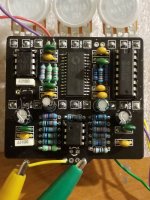
Maybe it's time to post some pictures
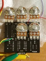
Sure. If it generates ideas---here are a few photos.

Note that things are looking a little worse for wear as we enter the frantic troubleshooting phase (you can see some board scuffs where I had a hard time removing C103 to replace it, which had no positive benefit in the end anyway).

The FV-1 has also now been removed/replaced several times on this board (the first one was taken off to use for something else), so the traces are a bit worse for wear, but under a magnifying glass the joints seem solid and all continuity checks out.

I've also used leads for the Density pot, as I had hoped to wire it through a switching jack for an expression pedal option.
2020-12-20 23.05.56.jpg
2020-12-20 23.09.08.jpg
 
Just want to verify that the 3 green resistors are actually resistors and not inductors. Green resistors used to be somewhat common, but nowadays the green bodied components are usually inductors.
 
Back
Top