Deflector Reverb - noise

owlexifry

Well-known member
first dabble at FV-1. first time using the 'basic relay bypass' board.
finished this a few weeks ago (pcb came with FV-1 presoldered)
was super excited.
sounds really cool.
just wish i could get rid of this noise

in this demo everything is at noon, except mix, which i turn up to noon to bring in the effect (and the noise) at the start.

- noise disappears when mix is turned all the way down.
- noise repeats with the echo repeats.
- noise isn’t really affected by altering positions of any controls (except mix)
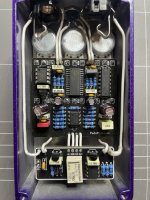
IMG_2664.jpeg

i thought it might be coming from the relay switch circuit, so i snuck in a 1N5817 between the relay circuit +9v supply, and that did nothing.

volts:
supply - 8.98v
after 1N5817 - 8.68v

tl072 pin8 - 8.68v

ic3
pin 8 - 3.34v
pin 6 - 3.33v

FV-1
pin6 - 3.33v
pin13 - 3.33v
pin14 - 3.33v
pin26 - 3.33v
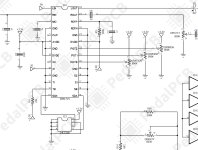
IMG_2665.jpeg

is there something i’ve done wrong?
where do i start looking?
 
It kinda sounds like jitter. Double check your component values around the clock portion of the circuit. If you have a scope, it may be worth looking at the clock in on the fv-1 to make sure it's stable.
A DMM with a frequency count may work as well.
 
may be worth looking at the clock in on the fv-1 to make sure it's stable.
A DMM with a frequency count may work as well.
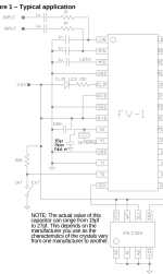
clock in = pin 10?
1711322501381.png

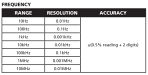
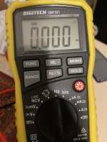
multimeter has a 'Hz' mode. is that any good?
1711323025388.png

what would 'stable' look like?

if it's a clock issue, perhaps i've damaged the CD4049 IC? (although adjusting the 'density' control indicates the clock speed is going up and down as it should)
 
clock in = pin 10?
View attachment 71411

multimeter has a 'Hz' mode. is that any good?

what would 'stable' look like?

if it's a clock issue, perhaps i've damaged the CD4049 IC? (although adjusting the 'density' control indicates the clock speed is going up and down as it should)
Yes, pin 10
If your meter can count it, you should see a steady count count, regardless of density position.
 
Yes, pin 10
If your meter can count it, you should see a steady count count, regardless of density position.
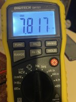
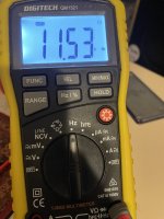
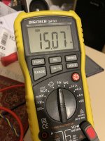
this cant be good then...

density @ minimum
IMG_2676.jpeg

density @ noon
IMG_2677.jpeg

density @ 1400
IMG_2680.jpeg

past 1500 and it'll do this
IMG_2678.jpeg

(all other controls at noon)

otherwise, the number stays fairly steady.. (if the position isn't changed)
 
Is that a TI CD4049? That may be your noise source. Perhaps you could probe the circuit before and after the CD4049, looking for noise. You can look elsewhere in this forum, @Chuck D. Bones has noted that those are quite noisy - he has recommended NOS RCA and National Semi instead. E.g., see https://forum.pedalpcb.com/threads/fun-with-cmos-part-1-the-cmos-raincoat.21449/post-271287
it appears to be TI.
perhaps i should try removing this cd4049, putting in a socket and trying another one?
 
although, would the noisy properties of a cd4049 really matter in this context where it’s not in the audio path and serving as an oscillator?
 
Last edited:
Good question, I honestly don't know. I didn't look at the circuit schematic and haven't ever investigated the FV-1. I would ping Chuck, although he may respond anyway - I believe that he's on US Pacific Time, so he likely needs more time.
 
With regard to your X1 frequency measurements above, note this on the FV-1 datasheet:

The crystal oscillator is designed for the standard 32768 Hz watch crystal, as this is particularly inexpensive, but any logic
level clock source can be attached to the X1 terminal directly. The sample rate of the system will be at this applied rate. At
32768Hz, the ADC and DAC bandwidth will be 15KHz, at a clock frequency of 48KHz, the bandwidth will expand to
beyond 20KHz. Watch crystals have a very high Q factor, and require significant time to develop full level oscillation. All
support components for the crystal are included internal to the device, including a 10Meg bias resistor and two 12pF
capacitors. The lead length however, between the crystal and the part must be as short as possible. Further, beware that
the loading of a scope probe on the X1 pin may cause the oscillator to stop. If you wish to check the oscillator's operation,
use X2 as a measurement point.
Depending on the supplier of the crystal there can be a startup problem with the crystal,
it is recommended that all designs include a 15pf capacitor between X2 and ground.
 
Does the noise still happen if the Deflect (bottom center) control is all the way down?

With regard to your X1 frequency measurements above, note this on the FV-1 datasheet:
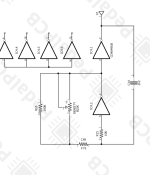
There isn't a crystal in this one, the 4049 is generating the clock signal so it shouldn't be quite as sensitive to loading.
 
Do you by any chance have any other FV-1 builds that you could borrow the EEPROM from temporarily?

Scratch that, I forgot this one has the input going into the right channel instead of left...
 
I still might suggest redoing your clock stability measurements using the X2 pin, per the datasheet

this cant be good then...

Because the Density control manages the clock rate, the clock rate will vary depending on the position of the Density control. It was designed that way. However, I would still consider the CD4049 as a source of the noise and socket it and try a different one.
 
Screenshot_20240325-070111-802.png
@Robert why was the 15-27pf differentiator cap was omitted on this build? Does it interfere with the density control at the extremes?
Wonder if the TI 4049s have some unwanted spikes that may be smoothed/filtered out with it.
IDK if the fv-1 prefers pulses over square wave clock but that seems it could cause a difference. Maybe @Digital Larry could give input on that.
@owlexifry do you have an o-scope? Would be nice to see if you are getting a clean clock cycle.
Also, if you haven't, double check your values around the clock circuit.
Screenshot_20240325-070049-861.png

I still might suggest redoing your clock stability measurements using the X2 pin, per the datasheet
I believe X2 is floating in this once per schematic.
 
Back
Top