SOLVED Delegate (Boneyard Edition): LED not changing with signal

jeffwhitfield

Well-known member
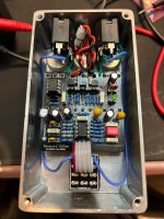
Hey folks! So...finished putting together a Delegate compressor last night. But after testing it a bit, seems something is askew. One thing I noticed is that the LED isn't changing with the signal. It just stays on no matter what...not even a flicker. Any suggestions on how to test things to reveal the problem? I mean...I could trace the board...but this could very well be a very simple thing. Figured I'd ask in case anyone happens to have had a similar problem. :p

IMG_0332.jpeg
 
Could it be working as intended? If you assemble the enclosure and don’t look at the light, what do you think?

Edit: I want to build a delegate but not sure which version. Maybe I’ll breadboard both and see how they compare.

Here’s a link explaining the changes made by @Chuck D. Bones
 
I think it's working as intended. Need to play around with it some more. I messed with a few different LED's and chose a 5mm green one that seemed to work a bit better. Also changed out the LDR with a different one. Need to play with a few other LDR's I have to see which one reacts the best.

Main thing I'd like is to have it work a bit like a limiter. Basically, Ratio all the way up so that transients like bass slapping and popping are knocked down a bit. I was kinda sorta getting there...but need to play with it more.

Man...optical compressors are weird! :p
 
No. Check out an Attack, Decay, Sustain, Release (ADSR) graph. ADSR graphs show the behavior of a note (e.g., piano keystrike, plucked guitar string, etc.) as a function of amplitude in the time domain. With the ATTACK and RELEASE controls, you're altering the behavior of those parts of the note's envelope. Unless very extreme, they are not binary on/off states, but rather ramping (visualized with varying levels of brightness). The LED's brightness affects the value of the LDR in the feedback loop of the op-amp. This is how the dynamics are modulated.

Also keep in mind that an LDR is going to be more sensitive than your eye. Especially if you're looking at an LED in a lit room, you might not see the subtle changes.
You had me at envelope. I actually started off as a keyboardist so, yeah, basically Envelope City. :p
 
Main thing I'd like is to have it work a bit like a limiter. Basically, Ratio all the way up so that transients like bass slapping and popping are knocked down a bit. I was kinda sorta getting there...but need to play with it more.
You may have better luck with a FET compressor if you’re looking for a fast attack response. VCA is also an option, but hunting down parts is a bit more difficult.
 
Jeff,
I'd like to help with troubleshooting, but first I need to know that you're willing to follow a systematic approach rather than switching parts around at random. Have you cleaned and inspected the board thoroughly? Any parts substitutions?

The LED should be on only when there is a guitar signal present. When the guitar signal gets louder, the LED gets brighter. It will flash during the initial transient and be barely visible otherwise. You have to test in complete darkness if the box is open.

Lets review how this pedal is supposed to work. With this many knobs, it's easy to get lost and some combinations do not work well. That is the price of having maximum control.
The SUSTAIN knob determines the maximum available gain. CW (clockwise) = more gain = more compression. A good initial setting is noon.
The RATIO knob determines how much the AGC (automatic gain control) loop can reduce the gain. CW = more gain reduction = more compression. A good initial setting is 3:00.
The ATTACK knob determines how quickly the AGC loop can reduce the gain during the initial transient. CW = slower response = louder initial transient. A good initial setting is 9:00.
The RELEASE knob determines how quickly the AGC loop can increase the gain after the initial transient. CW = slower response. RELEASE also limits the maximum LED current which might limit how much the ACG loop can reduce the gain. A good initial setting is 10:00.
The operation of the TONE & VOLUME controls is self-evident.

After you have verified that all solder joints are good, all parts are the correct value / part no. and are oriented correctly, we can proceed.

Work your way down this list until the answer is "no." Set ATTACK & RELEASE to 7:00.
If the LED is stuck on when no signal is present, the problem is most likely around Q1-Q3. That doesn't necessarily mean that Q1-Q3 are bad.

With the power off, remove IC1 from the socket and then apply power. Is the LED stuck on?

With the power off, remove Q1 from the socket and then apply power. Is the LED stuck on?

With the power off, remove Q2 from the socket and then apply power. Is the LED stuck on?

With the power off, remove Q3 from the socket and then apply power. Is the LED stuck on?

If you got this far and the LED is still stuck on, then either C10 is shorted internally or there is a solder bridge on the board.
 
I’ve also got the parts to build a thumb sucker. I figure I’ll bread board all 3 and see what stands out.

This 3 part series is a good read:

Jeff,
I'd like to help with troubleshooting, but first I need to know that you're willing to follow a systematic approach rather than switching parts around at random. Have you cleaned and inspected the board thoroughly? Any parts substitutions?

The LED should be on only when there is a guitar signal present. When the guitar signal gets louder, the LED gets brighter. It will flash during the initial transient and be barely visible otherwise. You have to test in complete darkness if the box is open.

Lets review how this pedal is supposed to work. With this many knobs, it's easy to get lost and some combinations do not work well. That is the price of having maximum control.
The SUSTAIN knob determines the maximum available gain. CW (clockwise) = more gain = more compression. A good initial setting is noon.
The RATIO knob determines how much the AGC (automatic gain control) loop can reduce the gain. CW = more gain reduction = more compression. A good initial setting is 3:00.
The ATTACK knob determines how quickly the AGC loop can reduce the gain during the initial transient. CW = slower response = louder initial transient. A good initial setting is 9:00.
The RELEASE knob determines how quickly the AGC loop can increase the gain after the initial transient. CW = slower response. RELEASE also limits the maximum LED current which might limit how much the ACG loop can reduce the gain. A good initial setting is 10:00.
The operation of the TONE & VOLUME controls is self-evident.

After you have verified that all solder joints are good, all parts are the correct value / part no. and are oriented correctly, we can proceed.

Work your way down this list until the answer is "no." Set ATTACK & RELEASE to 7:00.
If the LED is stuck on when no signal is present, the problem is most likely around Q1-Q3. That doesn't necessarily mean that Q1-Q3 are bad.

With the power off, remove IC1 from the socket and then apply power. Is the LED stuck on?

With the power off, remove Q1 from the socket and then apply power. Is the LED stuck on?

With the power off, remove Q2 from the socket and then apply power. Is the LED stuck on?

With the power off, remove Q3 from the socket and then apply power. Is the LED stuck on?

If you got this far and the LED is still stuck on, then either C10 is shorted internally or there is a solder bridge on the board.
Hey Chuck,

Thanks for this. It really, really helped. :)

I have a general knowledge on compressors and have used them in the past. Not an expert by no means...but I have a bit of knowledge on them. What I don't have is knowledge on how the circuits themselves work...especially an optical compressor. Very, very new to me. Main reason I started building a compressor was due to the fact that I changed the setup of my rig a bit. As a result, it required adding a compressor near the beginning of the chain in order to allow more flexibility. Anyways...

The part that really helped as the troubleshooting steps. Everything appeared fine in terms of the solder joints and I already checked all the values (I'll probably put the 220n caps back in now that things are working!). Where things got interesting was when I started removing the transistors. When I removed Q2, that's when the LED went completely off. With it in the LED is faintly on which, from my understanding, would cause the pedal not to work so great due to the fact that the LDR would always be triggered a bit by a faint LED.

Turns out that there was a short. Seems that there was something stuck between the mount points of the socket. That's a first for me so...new lessons learned: Always inspect and clean your sockets well after a build! Once I cleaned it out it all worked just fine. Always the little things. :p
 
Glad we got to the solution so quickly. This is one of the downsides to sockets, shit can get trapped underneath and it's hard to see.

Three LDR parameters things matter in optical compressors.
1. Dark resistance. The higher, the dark resistance, the more available sustain. You want at least 1Meg. Must be measured in TOTAL darkness. I put the LDR in a small cardboard box and close it up tightly.
2. Light resistance. The lower the light resistance, the more the compressor can lower the gain. You want no more than 10K. 12" or so from the work light at my bench is more than enough light.
3. Transient response. How fast does the LDR resistance changes from light to dark? The faster the response, the quicker the release. This requires a scope. If setting RELEASE to zero is not fast enough, try a different LDR.

The Delegate does not require a lot of light landing on the LDR. In fact, less is better. I use a standard brightness, diffuse green LED. There is about an 8mm gap between the LED and LDR. Too much light on the LDR slows down the release.
This is good to know. I read through a lot of forum post on the Delegate. I knew that the response time of the LDR was important. What I've been struggling with is the resistance. I think the one I have currently installed is likely too high....like 20K. I have four others so I know one of them will be perfect. Definitely have one that's 10K so no problem there. But what you outline here is a fantastic guide.

Always learning new stuff from you, Chuck! Definitely appreciated! :D
 
Back
Top