You are using an out of date browser. It may not display this or other websites correctly.
You should upgrade or use an alternative browser.
You should upgrade or use an alternative browser.
Diode Clipping Question
- Thread starter BuddytheReow
- Start date
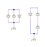
I don’t think parallel diodes facing the same way actually do anything different than just having one… so the one on the left would be symmetrical hard clipping with an extra redundant diode, and the one on the right would be assymetric hard clipping. (Forward voltage of the two series diodes add).
The one on the left, if the two diodes with anode to ground had different forward voltages, then only the one with the lower forward voltage would clip.
The one on the left, if the two diodes with anode to ground had different forward voltages, then only the one with the lower forward voltage would clip.
Feral Feline
Well-known member
Yup.
And the one on the right with two diodes in series, those two will have their forward voltages sum giving less clipping and more volume than the single anti-parallel diode they're paired with.
The parallel diodes on left would share the current load in something like a switching power supply, but for clipping I don't know.

 electronics.stackexchange.com
And the one on the right with two diodes in series, those two will have their forward voltages sum giving less clipping and more volume than the single anti-parallel diode they're paired with.
The parallel diodes on left would share the current load in something like a switching power supply, but for clipping I don't know.
Diodes in parallel or series
I am wondering what the effects are of putting diodes in parallel or putting them in series. (like current capabilities, voltage capabilities etc.) Let's say I have a datasheet of a diode. What
Last edited:
BuddytheReow
Moderator
Thanks, guys. Was wondering how best to put this on a breadboard project I'm working on right now.
Edit: For the example on the left, if I have a mixture of diodes would that change anything? I understand now that one would be redundant if they were identical diodes. What if one was a red LED and the other green?
Edit: For the example on the left, if I have a mixture of diodes would that change anything? I understand now that one would be redundant if they were identical diodes. What if one was a red LED and the other green?
benny_profane
Well-known member
Only the LED with the lowest Vf would conduct. The other would be redundant.
BuddytheReow
Moderator
ThanksOnly the LED with the lowest Vf would conduct. The other would be redundant.
Chuck D. Bones
Circuit Wizard
Yes.Is there any difference between these two as hard clippers?
View attachment 14947
Chuck D. Bones
Circuit Wizard
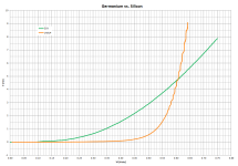
I used to think that was true, but it's actually not quite that simple. Vf is a function of current and some diodes have rather large resistance. If you put a silicon and germanium diode in parallel, the Ge diode will conduct most of the current at low currents, but as you raise the current, the Ge diode's Vf can exceed the Si diode's Vf. At that point, the Si diode conducts the lion's share of the current. The plot below shows some measured data comparing the D2V germanium diode with the 1N914 silicon diode. Below 4.7mA, the D2V conducts most of the current. Above 4.7mA, the 1N914 conducts most of the current. When we reverse-bias the Ge/Si pair, the Ge diode will conduct essentially all of the reverse current because Ge diodes are very leaky.I think on the example on the left, the signal will only see one diode in the pair that are oriented in the same direction. I'm guessing the one with the lower Vf?
benny_profane
Well-known member
I've always been curious about a ge and si diodes in series. It'd be great to be able to raise the Vf threshold and retain the characteristics of germanium clipping without requiring two or three in series in order to do so.
Chuck D. Bones
Circuit Wizard
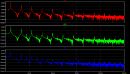
Am I right in thinking that all three diodes are the same part number?
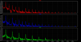
The fundamental freq looks like 670Hz, is that right?
Everything below -100dB is quantization error in LTSpice's digital calculations.
The fundamental freq looks like 670Hz, is that right?
Everything below -100dB is quantization error in LTSpice's digital calculations.
temol
Well-known member
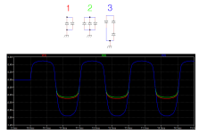
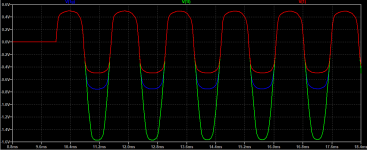
CDB - you're correct. 660Hz, only 1N4148 diodes.
Here - 1N4148, 1N34, red LED.
red trace - 2x1N4148, blue trace 1N4148/1N34, green trace 1N4148/red LED


And something interesting to read
And something interesting to read
 www.muzique.com
 www.muzique.com
 www.muzique.com
Here - 1N4148, 1N34, red LED.
red trace - 2x1N4148, blue trace 1N4148/1N34, green trace 1N4148/red LED
And something interesting to read
And something interesting to read
AMZ Warp Controls
Circuits for producing asymmetrical clipping in guitar distortion pedals.
AMZ Saturation Control
Circuits for Setting Distortion and Harmonic Levels in Guitar FX
AMZ Saturation Controls and Diode Clipping
Expanding the Tone of Diode Clipping with unique saturation controls.
Last edited:
Similar threads
- Replies
- 2
- Views
- 156

