Hello,
This is my first time making a post but I’ve been perusing for a few weeks so hello all.
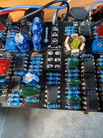
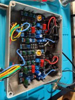
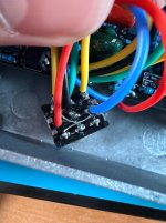
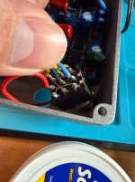
This is my first pedalPCB build but I’ve done a zepellin labs quaverato before and also I solder all my patch cables so I feel comfortable with an iron (although I did have trouble with the jacks and switches which I soldered post installation for cable management reasons). I also double checked all resistor, cap and transistor values prior to installation. Forget if I also tested the diodes, but I’m inclined to say I did. All parts from tayda.
My issue is the build turns on, the LFO’s seem to work by reading the oscillating led but I get a high pitched squealing that is way louder than the signal (which is currently also weaker than direct in, despite the bypass). I think the weak signal might be a ground issue on one of the jacks but I’m not sure, I confirmed continuity from ground to all sleeves and various points around the PCB.
So far for diagnosis I’ve tried, reflowing everything (some points even twice). Adding shielding to the back of the pots via electrical tape. Confirming ground continuity. And lastly (per some GPT walkthroughs that may or may not actually be helpful), I was voltage metering the individual IC’s to ground.
The IC’s gave me weird values that GPT said were off but I don’t have a great grasp of what I should be expecting. From the browsing I did it, GPT was expecting reasonable outputs/values. I got Pin 1, 2, 3, 5, 6 and 7 to be zero or near zero. And I got pin 4 to be -8.2V while pin 8 is 8.7V. GPT said this was due to a mid rail reference not working properly? Dont even know what that means or what it would entail but like I said I reflowed all the pads.
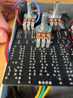
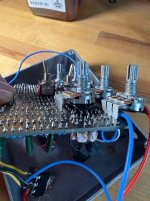
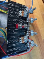
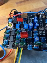
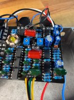
Attached a few pictures for reference in case I fudged something.
Thanks in advance! I am excited to get this figured out and get some whooshes going
This is my first time making a post but I’ve been perusing for a few weeks so hello all.
This is my first pedalPCB build but I’ve done a zepellin labs quaverato before and also I solder all my patch cables so I feel comfortable with an iron (although I did have trouble with the jacks and switches which I soldered post installation for cable management reasons). I also double checked all resistor, cap and transistor values prior to installation. Forget if I also tested the diodes, but I’m inclined to say I did. All parts from tayda.
My issue is the build turns on, the LFO’s seem to work by reading the oscillating led but I get a high pitched squealing that is way louder than the signal (which is currently also weaker than direct in, despite the bypass). I think the weak signal might be a ground issue on one of the jacks but I’m not sure, I confirmed continuity from ground to all sleeves and various points around the PCB.
So far for diagnosis I’ve tried, reflowing everything (some points even twice). Adding shielding to the back of the pots via electrical tape. Confirming ground continuity. And lastly (per some GPT walkthroughs that may or may not actually be helpful), I was voltage metering the individual IC’s to ground.
The IC’s gave me weird values that GPT said were off but I don’t have a great grasp of what I should be expecting. From the browsing I did it, GPT was expecting reasonable outputs/values. I got Pin 1, 2, 3, 5, 6 and 7 to be zero or near zero. And I got pin 4 to be -8.2V while pin 8 is 8.7V. GPT said this was due to a mid rail reference not working properly? Dont even know what that means or what it would entail but like I said I reflowed all the pads.
Attached a few pictures for reference in case I fudged something.
Thanks in advance! I am excited to get this figured out and get some whooshes going
Attachments
-
 IMG_0163.jpeg1.1 MB · Views: 24
 -
 IMG_0147.jpeg1 MB · Views: 23
 -
 IMG_0148.jpeg630.1 KB · Views: 18
 -
 IMG_0149.jpeg698.9 KB · Views: 18
 -
 IMG_0154.jpeg902.5 KB · Views: 21
 -
 IMG_0155.jpeg950.2 KB · Views: 21
 -
 IMG_0156.jpeg728.8 KB · Views: 24
 -
 IMG_0157.jpeg808.8 KB · Views: 24
 -
 IMG_0158.jpeg775.8 KB · Views: 21
 -
 IMG_0159.jpeg1 MB · Views: 22
 -
 IMG_0161.jpeg1 MB · Views: 23
 -
 IMG_0162.jpeg1 MB · Views: 27
