SOLVED Electrovibe Mini - LFO Not Starting

leadfoot

Active member
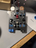
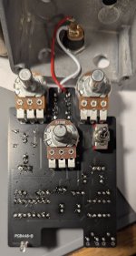
I am currently wrapping up an ElectrVibe Mini build and ran into the problem with the LFO not starting up. I can manually cause the bulb to increase in intensity via the gain and bias knobs and hear a change in the tone (as you'd expect in a Vibe), so I know the rest of the circuit works. It is just the LFO section that does not work.

The only modifications for the LFO circuit are:
r14, r15 - 1.5k
c8 - 2.2uF

I'm suspecting I might need to switch to tantalum capacitors as it appears to be leakage related as the potentiometers work as expected (tested via DMM resistor measurement), joints all appear to be fine as continuity appears ok.

1000003684.jpg
1000003683.jpg
 
Solution
My apologies if I missed something, I'm late to the party...

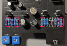
Check the values of these resistors.

They should be 4K7, it looks like you have 430R installed in each spot. That would very likely stall the LFO.

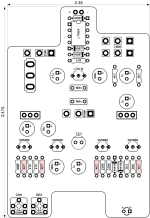
1752089971041.png

1752090211066.png
I built mine with elecs and the LFO works fine. Did you test it with the top board attached? Perhaps you need to install the spec components anre go from there
The top board works with no issues. It's the LFO that doesn't start. I can always desolder the 2.2uF and 1.5k resistors and switch to the 1u and 4k7 resistors but I would like to have a little more depth at slow speeds.
 
You may need those resistors to be 4k7 for the LFO to work

 
The top board works with no issues. It's the LFO that doesn't start. I can always desolder the 2.2uF and 1.5k resistors and switch to the 1u and 4k7 resistors but I would like to have a little more depth at slow speeds.

Depth at slow speed is dictated by the 2.2u cap.

Try swapping for a higher resistor value of R14/15.

I’ve personally never had issues with “lockup” of the LFO at 1.5k but who knows.
 
I changed r14/15 to 4k7 but still no luck. My assumption is that C8 is the capacitor between the two 4k7 resistors in the top right of the board below the c100k pot.
 
I would check all the other values and reflow all your joints before you start desolating more. Even the best of us (veterans of the hobby?) screw stuff up.
 
I would probably devote the most time to reflowing everything upstream of the electrolytic cap off the wiper of the intensity pot.

Does the lamp gain trimmer affect the brightness of the bulb?
The gain and bias trimmers both affect the brightness of the bulb.

I'll definitely focus on going backwards from that capacitor to the reference voltages.
 
Going to lob an idea out to look at as well: double transistor pinouts and voltages. I had an issue with the EQD Depths LFO stalling and checking/replacing the transistor and I think reflowing the leads to the dual gang potentiometer helped immensely.
 
At this point all that's left is to check the values of R34 and R35, and measure the resistance of the dual gang pot and see that it has the same value on both gangs.

Outside of that, make sure all your solder joints are clean. Even a tiny strand of solder shorting one joint to another can cause issues.

It's possible the entire LFO section isn't getting power from the L78L12 power IC. I'd check for voltage at R11 and follow it down the line
 
My apologies if I missed something, I'm late to the party...

Check the values of these resistors.

They should be 4K7, it looks like you have 430R installed in each spot. That would very likely stall the LFO.

1752089971041.png

1752090211066.png
 
Solution
Back
Top