Electrovibe Speed not working, POSSIBLY Switch wiring, Need help.

aienco

Member
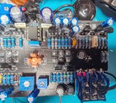
Hello, Been having a bit of a problem with the speed on my build. Originally had an issue with the vibe not working but traced that to a faulty Transistor at Q5. However, I still have NO speed on either control at any point. Speed LED constantly lit. I have followed another thread on here and tried the troublshooting there, but I was not sure whether I should be getting audio through the probe on the transistors, LDR's etc. I Dont have any Audio on the Speed Pots and I have been going round in circles for a day or so?
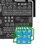
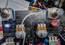
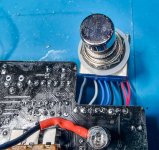
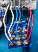
I had to use hard wired switches as the breakout boards, I managed to damage. I found the wiring for the speed switch on here, however I am not certain this is correct. I am just thinking, if the switch isn't working properly, then I am wasting my time with the other tests.

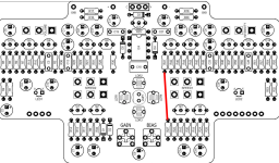
I am getting around 16V instead of 18V on Q2 & 4, The bulb is pulsing and the intensity is working. Its seems just the speed. But I have exhaused my knowledge and before I go changing all transistors and caps, I was hoping someone could give me some guidance. I tried a new Chip as well.
 

Attachments

  • 20230118_095317.jpg
    20230118_095317.jpg
    1.1 MB · Views: 40
  • 20230118_095332.jpg
    20230118_095332.jpg
    941.8 KB · Views: 38
  • 20230118_095336.jpg
    20230118_095336.jpg
    851.8 KB · Views: 38
  • 20230118_095348.jpg
    20230118_095348.jpg
    768.8 KB · Views: 42
  • sw-1.jpg
    sw-1.jpg
    837.3 KB · Views: 31
  • sw-2.jpg
    sw-2.jpg
    710.3 KB · Views: 26
Last edited:
Hi,

I'd say the soldering on the pcb's speed switch pads are very suspicious, I would start by sucking off a lot of the solder, with a desoldering pump. You need just enough solder to fill the pads. With too much solder, you may have a bad connection and shorts.
Good-and-Bad-solder-joints.png

Here is a link to the pdf file for other members who would want to help :


Edit : Once you have good solder joints there, you should clean the tiny spaces between pads to prevent shorts. Moving quickly with your iron, to avoid overheating the board.

Transistors and IC are heat sensitive, so it's always a good idea to socket them. This way you can easily remove them while you work close to them on the pcb.

Edit 2 : "I found the wiring for the speed switch on here, however I am not certain this is correct."

Where did you find it ? Can you give a link ?
 
Last edited:
I've tidied up a lot of the soldering. I have build over 100 kits in the last 40 years so I am not new to this. I use IC sockets, BUT I don't like transistor sockets because I have had times where they do not make good contact. You will notice, I usually leave the legs on transisters very long to absorb a little of the heat. This is an old day thing that I have always done.
Anyway, still not working.
 
So you are sure there are good connections and no shorts between pads on the pcb ?
20230118_095336.jpg
In that case, next I would trace the damaged switchboard (hoping you still have it) with a DMM, to know what goes where and make sure the switch wiring is correct.
I found the wiring for the speed switch on here, however I am not certain this is correct.
Can you give a link ?
 
Last edited:
This is what I found here in one of the posts where someone else had damaged their break out board. There was also a comment where another member had mentioned that it was correct??

I was hoping someone could confirm this is correct?? I tried tracing it from my breakout board, but it is a little too damaged.
 

Attachments

  • ElectroVibe Speed switch wiring.png
    ElectroVibe Speed switch wiring.png
    192.2 KB · Views: 10
Last edited:
I found this on the main electrovibe thread :

Looks different from your wiring on pin 4 and 5.

Reply #24 :
Hmm, you're right. I will play around with the combinations of the switch wiring as I am confident this is where the problem is.. Thanks.
 
Well after several combinations of wiring on the speed switch, still no better off.

Does anyone know, should I be getting audio with a probe on the speed pots Q1 and 2, etc with the Vibe switch in the off position??
 
Just an update. Probing around, I accidently jumped R27 & 41. See image. This started the speed control working????

Only problem is I am not knowledgable enough to know what to look for to fix this. I am sure putting a jumper across these two resistors permanently is not the correct fix??

The Light speed changes as I turn the speed controls, just no change in sound unless I put this jumper from 27 to 41??? I'm really confussed but I think this MIGHT be simple to someone with good electronics knowledge?

Appreciate any guidance.
 

Attachments

  • Layout.png
    Layout.png
    1.2 MB · Views: 11
Last edited:
Just an update. Probing around, I accidently jumped R27 & 41. See image. This started the speed control working????

Only problem is I am not knowledgable enough to know what to look for to fix this. I am sure putting a jumper across these two resistors permanently is not the correct fix??

The Light speed changes as I turn the speed controls, just no change in sound unless I put this jumper from 27 to 41??? I'm really confussed but I think this MIGHT be simple to someone with good electronics knowledge?

Appreciate any guidance.

Are you getting any phasing at all or just dry tone?
 
The circuit diagrams are broken up into four, showing power supply, signal path, LFO and Lamp driver.....

I Dont know how to tell where the signal is coming from to get to the LFO??? I am not sure how to read this on the circuit? I want to put a probe on the component/s that feed the signal to the LFO because I suspect, the signal doesn't get to that part of the circuit?
 
Just an update.... Things have gone from bad to worse. I decided to change a few components and whilst I was at it, I made the modifications. I used Tantelum capacitors in all places which might have been a mistake as now i am getting crackling through it when I engage the vibe and the speed issue is still non existant. I usually buy two of each board, because being in Australia, it takes 6 to 8 weeks to get the boards. This time I decided to buy one only. If I cant get it resolved, I'll have to shelve it and order another board. Its got me beat.
 
In the HOPE, that someone educated is still following this thread?? I have it back to where I started. That is to say it all works except the speed. I must have had a batch of faulty 2n5088's. I replaced all of them and it now works as it should however I get no speed change on 1 or 2.. Oh and I have applied all the mods as well. Hard to say whether there is any effect of the changes but as long as it hasn't made things worse, its great.


Any ideas PLEASE?
 
I Dont know how to tell where the signal is coming from to get to the LFO?
I think it's C14. Positive side.
There're 2 LFO symbols on schematics, in the LFO section between R14 and Q2, and in the Tube driver section near C14. I think that's the signal path.
Edit : sorry, this might be the LFO output...
 
Last edited:
I think it's C14. Positive side.

There're 2 LFO symbols on schematics, in the LFO section between R14 and Q2, and in the Tube driver section near C14. I think that's the signal path.

Edit : sorry, this might be the LFO output...
Thanks. Still gives me somthing to go on.... I just noticed now, the IC is getting very hot? Should it run hot???
 
Posting some voltage readings might help to find the issue. Someone might spot something. When I troubleshoot my builds, Old timers on forums always repeat : "readings, readings, readings".
 
Last edited:
Back
Top