[Ludicrous Speed OD] First attempt at a DIY pedal, not even turning on

adinapoli

New member
Good morning fine folks,

this is my first post ever and I hope to not be violating some rules or not posting in the correct section.

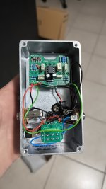
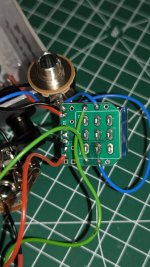
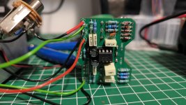
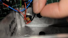
I have purchased a Ludicrous Speed OD kit from Musikding.de for which you can see the schematics here. Being my first attempt, and being relatively inexperienced with soldering, it sort of went decently (and learned how to do acceptable soldering along the way) but alas a few things went wrong, including me stupidly mounting the 3PDT board that they included upside down (i.e. flipped a-la pancake).

As it was too late to desolder (I have a desoldering pump, but it's very basic) what I have done was to treat the board as upside down so I have done all the wiring mirrored. However, once I have completed soldering, I have tried to stomp on the footswitch and .. nothing happened 🥹

I'll try to bring this to my in-law this weekend as basically he used to do this stuff before retirement, but a couple of questions are:

1. The obvious first step would be to use a multimeter (which I have) to check for continuity, but I'm a newbie using it. My intuition is that I should start from the power input jack and walk my way "upwards" (whatever that means) but I have no clue what to check first. Can somebody suggest a good initial step to check the obvious?
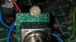
2. One of the first suspect I had was that I mounted the LED diode flipped (I have checked multiple times the anode and cathode but .. I'm human). Is there a way using the multimeter to check orientation? I have used the multimeter in the "diode/continuity" mode (I guess?) and placed the black end on the input power supply ground and if I touch one of the three leg (only a particular one) it "beeps", which I guess that means that is ground? What do I make out of this information?

Thanks in advance :)

Alfredo
 

Attachments

  • WhatsApp Image 2024-02-16 at 07.51.55.jpeg
    WhatsApp Image 2024-02-16 at 07.51.55.jpeg
    115 KB · Views: 32
  • WhatsApp Image 2024-02-16 at 08.30.21 (1).jpeg
    WhatsApp Image 2024-02-16 at 08.30.21 (1).jpeg
    234.3 KB · Views: 33
  • WhatsApp Image 2024-02-16 at 08.30.21.jpeg
    WhatsApp Image 2024-02-16 at 08.30.21.jpeg
    321.1 KB · Views: 30
  • WhatsApp Image 2024-02-16 at 08.30.22 (1).jpeg
    WhatsApp Image 2024-02-16 at 08.30.22 (1).jpeg
    272.8 KB · Views: 31
  • WhatsApp Image 2024-02-16 at 08.30.22.jpeg
    WhatsApp Image 2024-02-16 at 08.30.22.jpeg
    207.6 KB · Views: 32
Since you didn't install the current limiting resistor (CLR) on the 3pdt daughterboard, most likely you fried the LED.

The good news is that the signal effecting part of the circuit is independent of the LED, so it won't matter for the sound. Since this is a "transparent" overdrive, twiddle your knobs to make sure that you actually are getting no effect. If you still have issues, then visual inspection of component orientations is a good first step.

This requires a lot more spatial reasoning than I am immediately capable of, but if you respected the designations for terminals for each of the solder points on the daughterboard and main board (i.e.: in to in, out to out, etc.), I think the 3pdt should be okay (??) The other thing is it looks like the daughterboard has a lot of different designations and empty solder points, so to make doubly sure that you are connecting to the right points.

You should also include a shot of the other side (solder side rather than component side) of the board, as that's usually where problems occur. Make sure, for example, that your potentiometers backs are insulated from the soldered leads.
 
Last edited:
Hi, thanks for the reply. It's upsetting because Musikding didn't include any CLR in the kit.. should it have?

Either way, I have tested the LED with my multimeter in diode mode and, despite a very dim light , it seems the LED it's still alive.

I will try to get better shots when I can.
 
Since you didn't install the current limiting resistor (CLR) on the 3pdt daughterboard, most likely you fried the LED.

The good news is that the signal effecting part of the circuit is independent of the LED, so it won't matter for the sound. Since this is a "transparent" overdrive, twiddle your knobs to make sure that you actually are getting no effect. If you still have issues, then visual inspection of component orientations is a good first step.

This requires a lot more spatial reasoning than I am immediately capable of, but if you respected the designations for terminals for each of the solder points on the daughterboard and main board (i.e.: in to in, out to out, etc.), I think the 3pdt should be okay (??) The other thing is it looks like the daughterboard has a lot of different designations and empty solder points, so to make doubly sure that you are connecting to the right points.

You should also include a shot of the other side (solder side rather than component side) of the board, as that's usually where problems occur. Make sure, for example, that your potentiometers backs are insulated from the soldered leads.
If he didn’t include the CLR, the LED would never see any current, unless he jumpers it as the CLR is in series with the LED and not parallel, so the LED would likely be fine if he simply pops in a resistor (4.7k is a good starting point)
 
The first step in troubleshooting is to not talk about trou….. no, wait…check all your components to make sure they are correct and the polarity is correct. The next step would be to go back and reheat the solder joints so the solder flows through the holes.
 
It doesn't matter if the 3PDT pcb is flipped wire it as normal it's symmetrical

You've probably got the jacks the wrong way around If you get bypass flip the cables around and that'll confirm the jacks need swapped then just wire the in's to the left and outs to the right

All your component values and orientation that I can see look correct
 
Last edited:
Thanks folks. I will first try to acquire a new resistor for the CLR, and see if that allows the Led to turn on. I have done a bit of continuity checking today and resoldered a few points , and at least I'm getting continuity between IN and OUT (from the PCB) next would be checking jacks continuity and finally dig into voltage measurement.

I am a bit upset that my first kit ever was doomed to failure due to the missing CLR, sob.
 
It connects like this so as I say if you flip it, it's symmetrical so crossing your wires over as you have means the input signal from the in jack connects to the pcb out so won't go through the circuit

Do you get bypass signal? if not that indicates another fault

*When I said previously flip your cables I meant your guitar and amp cables going into the pedal that'll confirm very quickly it's wired backwards

Screenshot_20240216_185231_AdobeAcrobat_copy_540x493.jpg
 
It connects like this so as I say if you flip it, it's symmetrical so crossing your wires over as you have means the input signal from the in jack connects to the pcb out so won't go through the circuit

Do you get bypass signal? if not that indicates another fault

*When I said previously flip your cables I meant your guitar and amp cables going into the pedal that'll confirm very quickly it's wired backwards

View attachment 68637

No, alas I'm not getting any bypass signal even, so I'm afraid I have screwed up big time. Also, while checking continuity I have realised I have also swapped the pots of the volume and drive.

Perhaps kickstarting my career of hobbyist pedal builder with two small twins was a mistake, this sounds like the kind of mistakes easily avoidable if you are not sleep deprived :)
Successful on the first try builds are cool, but it’s the ones you have to work for, like this that are the most rewarding… and most educational!

Trust me, with twins, you’ll need the distraction of pedal building to help keep it all together!
 
Check your stereo input jack you should get bypass regardless of power or whether you've got your jacks backwards

Make sure you haven't accidentally mistaken the ring connection used for the battery ground with the tip connection just stick a jack in and trace the tip connection round to its solder lug like this

View attachment 68643
Thanks a lot for your help, I will take a look over the weekend and report back!
 
This looks like board has different options for top or side jacks, with or without the daughterboard. Since it looks like you can stick the led in the main board, you may have just soldered the CLR in the place designated for it in the main board instead of the daughterboard

The CLR is just a regular resistor, as somebody said, usually a 4k7.

Again, any issues with the LED should have no effect on the signal processing in the main board. If you have no signal, then it's wiring to power/in or out jacks, switch, or something incorrect in the main board.
Ah, in fact, in that building instructions that I have posted, there was this text under the picture of the daughterboard:

Note: If wiring the LED to our 3PDT board no need to connect S4, S5 & S6 or populate D6 or
R10 (CLR) on the main board since you are wiring your LED directly to our board.

I guess this means I shouldn't have soldered R10 at all, and instead solder it as a CLR (even though it has quite less resistance than the advocated 4k7.

Can I leave the R10 alone and Just solder the additional CLR?
 
Thanks folks. I will first try to acquire a new resistor for the CLR, and see if that allows the Led to turn on. I have done a bit of continuity checking today and resoldered a few points , and at least I'm getting continuity between IN and OUT (from the PCB) next would be checking jacks continuity and finally dig into voltage measurement.

I am a bit upset that my first kit ever was doomed to failure due to the missing CLR, sob.
Don't get discouraged... Just learn as much as you can along the way.
 
Ah, in fact, in that building instructions that I have posted, there was this text under the picture of the daughterboard:

Note: If wiring the LED to our 3PDT board no need to connect S4, S5 & S6 or populate D6 or
R10 (CLR) on the main board since you are wiring your LED directly to our board.

I guess this means I shouldn't have soldered R10 at all, and instead solder it as a CLR (even though it has quite less resistance than the advocated 4k7.

Can I leave the R10 alone and Just solder the additional CLR?
Just desolder and resolder r10 is what I would do. Good practice. If the pump don't work, heat one lead and then the other while pulling on the resistor, should come out easily enough. The resistor will be fine, and it doesn't matter if you kill the pad or trace at r10
 
Just desolder and resolder r10 is what I would do. Good practice. If the pump don't work, heat one lead and then the other while pulling on the resistor, should come out easily enough. The resistor will be fine, and it doesn't matter if you kill the pad or trace at r10
Ok, time to test out my cheap 5 euro Amazon desoldering pump 😅
 
Ok, time to test out my cheap 5 euro Amazon desoldering pump 😅
If you have one, that's great. You can also get away with a soldering iron, a pair of tweezers and some some desoldering braid. If you get stuck trying to remove, desolder, or replace components, I've been there dude, and I'm happy to share my experiences with you if it helps...
 
Back
Top