SOLVED Germanium fuzz not working

Johnnyorange500

Active member
Hi,


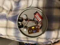
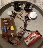
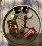
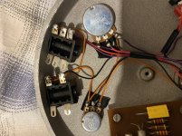
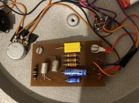
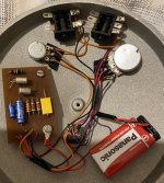
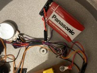
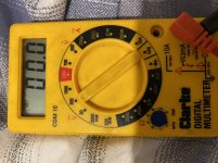
I’m having a bit of trouble with my Germanium fuzz face build. I seem to think I’ve soldered every wire correctly but I’m not getting any fuzz through the pedal. There’s just a dry guitar signal coming through the bypass and it also switches it off too. So I’m guessing the foot switch and input and output jacks are fine. I’ve just bought a new 9v battery too. All the capacitors and transistors are giving off an electric reading so they haven't burned out. I’m completely baffled as to why it’s not working. Would be very great full for some advice.


Johnny
 
Managed it
 

Attachments

  • 411AEC24-F905-48CE-8FB2-3E17DA71996C.jpeg
    411AEC24-F905-48CE-8FB2-3E17DA71996C.jpeg
    29.5 KB · Views: 26
  • 6A03D370-E922-4B8F-9A9E-837D88157924.jpeg
    6A03D370-E922-4B8F-9A9E-837D88157924.jpeg
    44.6 KB · Views: 25
  • 53A5FAAE-6F89-4E2D-BBF7-AC50FE85C49A.jpeg
    53A5FAAE-6F89-4E2D-BBF7-AC50FE85C49A.jpeg
    695.7 KB · Views: 23
  • 5073247B-72B8-4607-8B25-5E051DE2A179.jpeg
    5073247B-72B8-4607-8B25-5E051DE2A179.jpeg
    478.1 KB · Views: 22
  • A7F4089C-990C-4387-899D-343397FAFC2F.jpeg
    A7F4089C-990C-4387-899D-343397FAFC2F.jpeg
    419.6 KB · Views: 20
  • 04F8B8B9-F7E9-43E8-A682-1B363F5496B7.jpeg
    04F8B8B9-F7E9-43E8-A682-1B363F5496B7.jpeg
    645.2 KB · Views: 16
  • D64F88B2-F8A7-4025-8336-1E17F9DADB2F.jpeg
    D64F88B2-F8A7-4025-8336-1E17F9DADB2F.jpeg
    374.5 KB · Views: 20
Sorry guys I’m pretty new to using this so if you could point me in the right direction to what selection to use.
 

Attachments

  • 79D9B70C-C09D-465D-8D51-2C73BE4AABF4.jpeg
    79D9B70C-C09D-465D-8D51-2C73BE4AABF4.jpeg
    354.9 KB · Views: 6
BTW, I'm looking at the pictures and it looks like you sent the red wire to the pot ? and black to the board. I would suspect that to be reverse polarity. You red should be the + and go to you board.. no ?
 
Positive ground? Also, I think this is a production unit.
Well standard 9V battery connectors would have positive on the red wire and negative on the black wire. I can't see a red wire going to the board form the battery, it look like it's going to a pot or to a jack... that would make me think he's sending positive to the ground rail and the ground wire to VCC rail.
 
Well standard 9V battery connectors would have positive on the red wire and negative on the black wire. I can't see a red wire going to the board form the battery, it look like it's going to a pot or to a jack... that would make me think he's sending positive to the ground rail and the ground wire to VCC rail.
Hi, so I’ve made a mistake? What do I need to do to rectify it so it will work. So follow what you’ve said on this about changing the battery wires.
 
Hi, so I’ve made a mistake? What do I need to do to rectify it so it will work. So follow what you’ve said on this about changing the battery wires.
Ok before you change anything please confirm the following:

Where does the red wire of the battery connector go ?
Where does the black wire of the battery connector go ?
If you put your red probe on the solder point of the red wire battery and your black probe on the solder point of the black wire, do you read +9V or -9V ?
 
Back
Top