
Yes! That is exactly where it is. The green circle. And conductivity is still present between the two transistor leads. Thanks!Is this the Area in the green circle that the trace is showing.
You should have Continuity on that trace between the two Transistors with Red Circles?
View attachment 47579
You are using an out of date browser. It may not display this or other websites correctly.
You should upgrade or use an alternative browser.
You should upgrade or use an alternative browser.
How do you desolder the dpdt toggle switch without burning up the board
- Thread starter davidlay
- Start date
Dude, I hate to be the bearer of bad news, but you’re gonna have A LOT of desoldering to do. Those op amps are flipped, and you soldered them in. You really need to get some sockets for the op amps!! If i was you, I’d order a new board, seeing as it’s your first build. You’re gonna be chasing gremlins on this thing forever. And, when you order components, always order more than you need. It never hurts to have 10+ extra caps and resistors on hand. With pots, if you need two, order four, same with switches. That way if/when problems arise, you don’t have to wait for a lengthy Tayda order. If you do desolder those op amps, I wouldn’t use them again, because they’ll probably be burnt up from too much heat from soldering and desoldering. Hope that helps!
Feral Feline
Well-known member
Most of my components arrived. I am now waiting on a switch and a power jack and some kapton tape to cover up a part where one of the pathways got exposed. I think the switches that are coming may be type 1 and not type 2 so that may require a workaround. Some on here have said that they can be popped open and the elements flipped but I will need to test if which type it is first with a multimeter. I think the difference is the diagonals on the center position. Thanks to everyone for being so helpful.
re switch manipulation:

I've turned a type 1 into a type 2 by disassembling, flipping internal-bit, and reassembling ... it's fiddly, and not guaranteed successful.
I had to disassemble and reassemble a number of times before the switch behaved correctly — every time you rip it apart though, you're causing wear-and-tear on the switch-bits and getting closer to a switch that either won't work at all or will fail sooner than a non-tampered switch.
You have to be pretty confident in your workmanship and that procedure to then solder it into a PCB afterwards, given that it'll be more prone to failure.
Best to save that doctored DPDT for a project with offboard wiring than for a PCB.
re Exposed traces:
I've used clear nail-varnish to paint over exposed traces, in the past.
re Backwards soldered-in ICs that [Drayve85 noted that Music6000] spotted
Here's a suggestion...
Put the Hyped Fuzz on the back-burner; Get another simpler project to work on:
- a fuzz such as the Copper Clad Fuzz, Barrage Fuzz, SiliSmile Fuzz — since you wanted a fuzz to begin with;
or
- a boost is always useful, such as the Aft Preamp, Amentum Boost, Black Tiger, or Enchanted Boost.
After you've got more solder-time under your belt, you can revisit your Hyped Fuzz to fix it.
[Edited for attribution]
Last edited:
YEP!!! My first build, I bought two Refractor boards from Aionfx, which are their Klon Klone. Luckily, my dad helped me with them, so they both eventually worked, BUT I should’ve definitely picked a simpler circuit. Less to go wrong, better chance of getting it up and running with the least amount of trouble. Try a Zendrive, or Timmy, or a light speed. Good circuits and great sounding overdrives!Yeah. I can only echo the advice here. Grab a simpler kit to start off with, less to go wrong and there are a lot to choose from!
I think most of us fell in that trap, first build and we want to go for something which excites us!
kweefthief
Active member
Hey sorry to open up this old thread!Toggle's & Footswitches are the hardest to remove.
The pro's use a special tip that heats all six pins at once so it just falls out!
If you want save the Board you may have to sacrifice the switch.
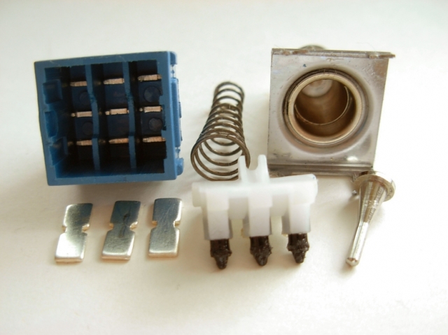
You have to disassemble the switch like pictured below & then you can push the pins out one at a time while applying heat to the pin.
A toggle switch is basically the same internally.
UPDATE: I wrecked this switch for Nothing! Ha Ha!, It was one of those Long Handle ones anyway!
So pry it apart like in first picture below & just put soldering Iron on Pin, solder gets hot & just push so it drops through into the plastic capsule!
View attachment 46987 View attachment 46988
I was trying to figure out how to do this and came across your post! I ran into a problem where I snapped off the lever and threaded part and need to replace the switch. Problem is Im not sure how to disassemble/pry it apart it like you did these pictures!
Any advice would be greatly appreciated!!!
Here's a pic of my sad little switch...

That's why I always leave the bottom nut on so when you tighten the top nut it pulls on the bottom nut not the tin chassis.Hey sorry to open up this old thread!
I was trying to figure out how to do this and came across your post! I ran into a problem where I snapped off the lever and threaded part and need to replace the switch. Problem is Im not sure how to disassemble/pry it apart it like you did these pictures!
Any advice would be greatly appreciated!!!
Here's a pic of my sad little switch...
View attachment 64462
Just lever the sides open & the metal clamp will just pop off with the little claws:
