
I started what was to be my first pedalpcb build. The hyped fuzz. After tayda forgot a few parts i had to order some additional components and decided to solder the ones i have. i screwed up and put the switch on the wrong side and have been hitting it with the solder sucker to try and get it off the board but it wont come off. i dont want all the work, time and money i did spend to be for nothing. any ideas?
You are using an out of date browser. It may not display this or other websites correctly.
You should upgrade or use an alternative browser.
You should upgrade or use an alternative browser.
How do you desolder the dpdt toggle switch without burning up the board
- Thread starter davidlay
- Start date
Erik S
Well-known member
I don’t think I’ve had to desolder a dpdt, but I definitely soldered some pots on the wrong side, and I’ve desoldered some spdts.
I’d say be patient, keep going back with the sucker, and when you think you’ve removed as much as possible, try heating one lug at time while gently pulling / wiggling the switch from the other side. Too much wiggle could definitely rip the traces off the board, so be careful. I’ve never had one just fall out though, they always need a little coaxing.
I’d say be patient, keep going back with the sucker, and when you think you’ve removed as much as possible, try heating one lug at time while gently pulling / wiggling the switch from the other side. Too much wiggle could definitely rip the traces off the board, so be careful. I’ve never had one just fall out though, they always need a little coaxing.
Toggle's & Footswitches are the hardest to remove.
The pro's use a special tip that heats all six pins at once so it just falls out!
If you want save the Board you may have to sacrifice the switch.
You have to disassemble the switch like pictured below & then you can push the pins out one at a time while applying heat to the pin.
A toggle switch is basically the same internally.
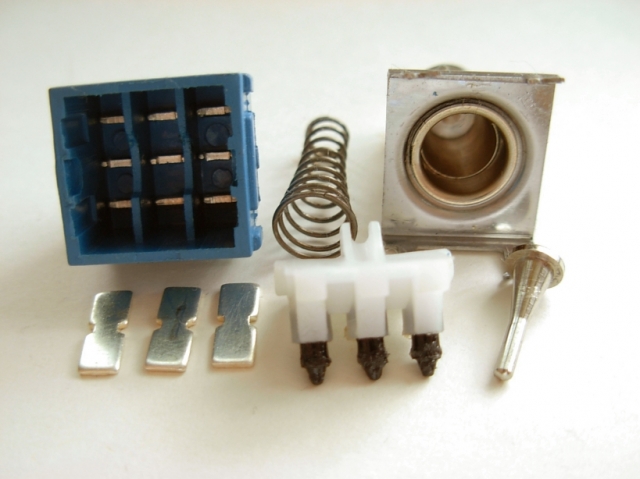
UPDATE: I wrecked this switch for Nothing! Ha Ha!, It was one of those Long Handle ones anyway!
So pry it apart like in first picture below & just put soldering Iron on Pin, solder gets hot & just push so it drops through into the plastic capsule!


The pro's use a special tip that heats all six pins at once so it just falls out!
If you want save the Board you may have to sacrifice the switch.
You have to disassemble the switch like pictured below & then you can push the pins out one at a time while applying heat to the pin.
A toggle switch is basically the same internally.
UPDATE: I wrecked this switch for Nothing! Ha Ha!, It was one of those Long Handle ones anyway!
So pry it apart like in first picture below & just put soldering Iron on Pin, solder gets hot & just push so it drops through into the plastic capsule!
Last edited:
Thanks everyone. I was starting to think that sacrificing the switch was necessary to save the board. Breaking it apart and desoldering tab by tab worked. I will order a new one. Hopefully I did not burn up the pathways in the board trying to desolder it. Fortunately I have a temperature controlled iron and was just running at 625 for the most part. A few moments at the hottest were only touching the tips of the tabs and careful not to touch the actual board. I started off simple changing the LEDs on existing pedals to blue ones as practice, then changing the LEDs on my Mesa footswitch. Decided to take on building a whole pedal as the next step.
Paradox916
Well-known member
Good equipment can make all the difference, even if you are only semi serious about the hobby (like me) you can get a cheaper hot air rework station ( mine was about $60)and those things are worth it in situations like this, It has saved my a$$ from mistakes more than I can count. Plus makes SMD stupid easy, and no more burn marks on heat shrink
jimilee
Well-known member
Got a link?Good equipment can make all the difference, even if you are only semi serious about the hobby (like me) you can get a cheaper hot air rework station ( mine was about $60)and those things are worth it in situations like this, It has saved my a$$ from mistakes more than I can count. Plus makes SMD stupid easy, and no more burn marks on heat shrink
Paradox916
Well-known member
Limited-time deal: YIHUA 959D-Digital Hot Air Rework Station, High Power with 3 Memories, Airflow Efficiency, °F /°C Display, Accurate Temp.(212°F~932°F), Brushed Aluminum Panel & Safety Features https://a.co/d/6E47n2PGot a link?
That’s the one my wife got me, and it’s been working great, it’s definitely not something that gets real frequent use but when I do need it, it’s really nice to have,

Good Luck depends on who the faulty Switch belonged too, you or somebody else had a dud switch to replace which is not Good???

But Well Done!
I don't do this for everybody but coz your off to a bad start down the rabbit hole, here is a Test you can do while you wait for the New switch to arrive that will go on the opposite side of the PCB Board.I started what was to be my first pedalpcb build. The hyped fuzz. After tayda forgot a few parts i had to order some additional components and decided to solder the ones i have. i screwed up and put the switch on the wrong side and have been hitting it with the solder sucker to try and get it off the board but it wont come off. i dont want all the work, time and money i did spend to be for nothing. any ideas?
With the PCB unplugged & with your DMM, check for Continuity with the matching Colours to make sure your PCB is OK! :

Thanks so much! All of these appear to beep with application of the multimeter. Some were a continuous beep. I think a couple did a short beep but enough of a beep to know a connection was there. This could be due to the fact that most of the components were already soldered on. Ultimately I will know when the rest of the components arrive. Another interesting thing is that I also had to use a 2.4k resistor in place of the 2.2k because no 2.2k resistors were available at the time of the initial order. It will be interesting to see how much this changes the sound if everything is indeed a go.I don't do this for everybody but coz your off to a bad start down the rabbit hole, here is a Test you can do while you wait for the New switch to arrive that will go on the opposite side of the PCB Board.
With the PCB unplugged & with your DMM, check for Continuity with the matching Colours to make sure your PCB is OK! :
View attachment 46885
Most of my components arrived. I am now waiting on a switch and a power jack and some kapton tape to cover up a part where one of the pathways got exposed. I think the switches that are coming may be type 1 and not type 2 so that may require a workaround. Some on here have said that they can be popped open and the elements flipped but I will need to test if which type it is first with a multimeter. I think the difference is the diagonals on the center position. Thanks to everyone for being so helpful.
fig is Correct, not worth the risk!
You took on a challenge being new to this with this Build for starters, there is a lot of components & expense involved.
We have not seen the PCB or the Solder work on the Back of the board as we are talking about pads that are really close together & prone to bridge each other.
Can you take some Good quality pictures & post them here so we can see what we are dealing with?
Here is a LInk that I posted for those with Build issues :
 forum.pedalpcb.com
forum.pedalpcb.com
forum.pedalpcb.com
You took on a challenge being new to this with this Build for starters, there is a lot of components & expense involved.
We have not seen the PCB or the Solder work on the Back of the board as we are talking about pads that are really close together & prone to bridge each other.
Can you take some Good quality pictures & post them here so we can see what we are dealing with?
Here is a LInk that I posted for those with Build issues :
Important: Supplying Pictures when an Issue arises with a PCB Build !!!
I have to raise this ongoing issue when Members ask for Help with an Issue with their Build. I keep repeating this saying '' Pictures are worth a Thousand Words'' !!! Please supply Pictures of PCB & ALL connections ( Footswitch, Input & Output Jacks, Power Jack ) to it along with a clear...
Important: Dust Covers for 16mm Potentiometers!
I believe this is mandatory for Dust covers on Pots under the PCB. It is a on going Issue that should be standard practice in Builds. This stops the PCB from shorting out on the metal back of the Pot : They come standard with Tayda Alpha 16mm Pots. UPDATE: Alpha stopped supplying Tayda Pots with...


Thanks for the tips. Some components from Tayda were wrong so that is why they were missing. I had to order the replacements. As of now, all but one of the electrolytics are on there now, and the one 10uf at the top that is missing is only off because I am waiting on some kapton tape. As for the pots, I am waiting on the rest of the components to show just in case they get in the way as well as the power jack which still is not here and which Tayda sent the wrong thing. I forgot that my top pic is out of date and I should probably take another.
Take this as a Guide to Help you, this is how you will learn.View attachment 47461View attachment 47462
On the top pic, below the one missing electrolytic capacitor is where some of the trackways appear to be exposed. as for the underside pic, this is where the switch lugs look messiest but the multimeter seems to detect conductivity in all of them per the provided diagram.
My Observations:
1. 1/8w Resistors not used, this will freek some people out including me as using 1/4w Resistors standing up just makes it impossible to see if the values are correct.
2. Do you see an issue with the 2 - 4558D Op Amps?
Answer - The Dot represents Pin 1 which is on the Top Left corner so it needs to be rotated 180 degrees.
3. Why are the Electro's missing?, There is Solder on the Back where they once were.
4. You haven't Fire it up yet as the Pots & Footswitch have not seen Solder yet.
.jpg")
WonkoTheSane
New member
I use a Hakko desoldering iron and some leaded rosin core solder added here and there to loosen up the lead free stuff, at least on commercial things. The solder lots of companies use melts at a very high temp, enough to destroy the part and the circuit board itself very easily. Some flux always helps too, but some solder is very stubborn, have to be patient.
I have almost all the components I ordered now except the kapton tape. I'm waiting on that to arrive so I can solder in the last electrolytic, then flip the two JRC4558 chips around, and finally put the pots on because they will block a number of other components. As for the resistors, all of them are the correct value except the 2.2k resistor which was subbed with a 2.4k resistor because that was all I could find at the time. The 2.2 was missing from my order. My push switch is already on its breakout board (got that one soldered correctly thankfully) and it's just a matter of tying them together. My switches arrived as well. The first two ended up being type 1 so I had to open them up and flip the notched cups around, breaking one in the process. The second set of two switches arrived as well and thankfully those tested as type 2 from the start. At this point in time I'm just waiting on the kapton tape because the exposed trackways under the top 10uf electrolytic or where it should go anyway kinda bug me.
Similar threads
- Replies
- 4
- Views
- 232