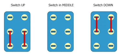
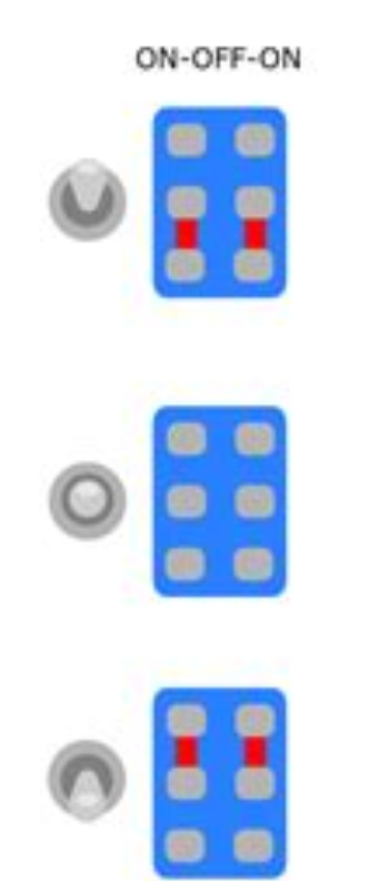
You could have the clipping all on one switch, a 4PDT on-off-on, for both clipping stages.
(think of it as having two DPDT switches with only one lever for both)
That won't be as versatile as having two separate DPDT on-off-on, but you may want just two or three distinct sounds.
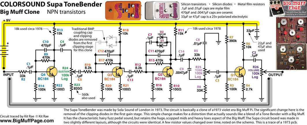
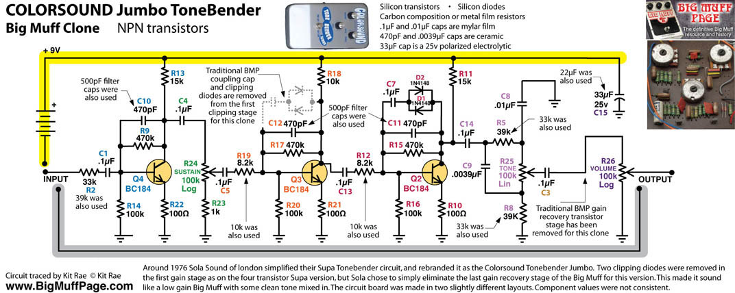
Either way, you can go into Supa/Jumbo ToneBender mode ...
Do you breadboard at all?
You could see which options really flip your switch, and in turn reduce switches on the pedal, save some dosh. Not sure what the price difference is between a single 4PDT and 2 x DPDT. Yet another option is to just have a toggle on the first clipping stage (or just the second).
Some people love tweaking and want all the options, others want things boiled down to what they like and actually will regularly use.
When I started DIY, I used to want all the options because I could, but now I'm beginning to see that minimising option-paralysis can be good, too. I mean, you can fit a LOT of 3PDT stompers on a 1590BB, but how dexterous are your toes? Practicality has a limit. Anyway, a couple toggles is no problem.
You could even wire up a 4PDT footswitch (on-on) to stomp between two flavours of clipping, though there may be a volume difference.
As mentioned, many ways to wire a switch.
It's like 3PDT wiring for bypass, there are a number of ways to do it — after trying a few (or all) of them you'll most likely gravitate to one way of doing it that makes the most sense to you, it becomes your preferred method.
I'll suggest...
1) decide what exactly you want to do, then
2) see if there's a feasible way to do it, and if not
3) revise "1)".
Rinse, repeat.