Ratimus
Active member
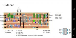
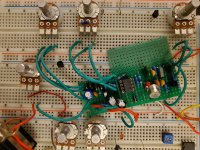
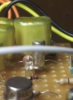
YATS, with asymmetric clipping (LED & Ge+Si) into a Baxandall. Sounds pretty good. A fella on Facebook bought one and took a bunch of gut shots, which he sent to me for tracing. The originals are on vero board, so I feel pretty confident tracing this one just from the pictures (especially since I can keep asking him for component values and such). I'll post the schematic once I draw it up.