SOLVED Isosceles Boost Issues: tiny/no signal when engaged?

devito

New member
Hey all! I am having some trouble with an Isosceles Boost build. This isn't my first pedal or even my first Isosceles. Pedal "works", but output is very quiet unless you play really hard, in which case the little bit of sound that comes out sounds a lot like a gated fuzz / spitty / etc.

Things I've checked so far:

1. Solder joints.
2. Replaced both chips with confirmed working versions (TL071 and TC1044SCPA). No change.
3. Replaced BC550C. Perhaps I had two bad ones in a row but... no change.
4. Compared all the orientations of things etc to my working Isosceles and everything is correct.

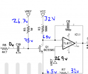
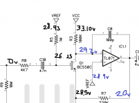
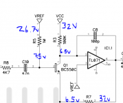
I am pretty meticulous about testing everything before I put it in, I don't remember anything reading incorrectly. I know my way around a multimeter/schematic and I've been tracing the circuit and haven't found anything strange yet. Any suggestions? I can add pictures or video if needed.

Cheers!
 
voltage readings on the ICs and transistor?
Hey thanks for the reply. Sorry I'm just getting to it.

For the TC1044SCPA:
(left side, top to bottom)
1. 9.50v
2. 4.86v
3. 0v
4. 0.13v
(right side, bottom to top)
5. 0v
6. 4.72v
7. 6.08v
8. 9.50

For the TL071:
(left side, top to bottom)
1. 0.28v
2. 7.60v
3. 26.8v
4. 0v
(right side, bottom to top)
5. 0.16v
6. 32.02v
7. 32.7v
8. 0v

For the BC550C:
C. 7.11v
B. 7.64v
E. 7.06v

I also have 32v present at the kathode side of D106.
 
Last edited:
Interesting find: if I suspend SW1 in the in-between state, aka, I get it right in the middle where only the center lug is active, I get signal + working level knob. If I switch it up or down per normal, I get nothing. I think I've traced this whole circuit for continuity and everything is right there. From my research, I feel like the transistor BC550C is not supposed to be the same voltage on all 3 points, b/e/c. Here's a picture of voltage readings from around Q1 if it helps. Seems weird to me but I don't know exactly why.
 

Attachments

  • Capture.PNG
    Capture.PNG
    25.2 KB · Views: 10
Last edited:
I’m having exactly the same issue :(, did you solve it ? Any advice you can give me ? Thanks
TAKE MY ARM!!! WE SUFFER.....AS ONE!

... I haven't fixed it, but I built an audio probe and damn I wish I made this a day ago. Let me get you a link. It absolutely changed the game when it came to diagnosing the issue and would've saved me so much time if I had made it a few days ago.

I just figured out that I am getting no signal on pin 6 of the TL071, aka, the output of the Op-Amp. So I am now trying to figure out why. I will absolutely update you if I figure it out! Hopefully someone wiser than I can help!
 

Attachments

  • audio_probe.gif
    audio_probe.gif
    4.8 KB · Views: 7
I’m having exactly the same issue :( in, did you solved it ? Any advice you can give me ? Thanks
TAKE MY ARM!!! WE SUFFER.....AS ONE!

... I haven't fixed it, but I built an audio probe and damn I wish I made this a day ago. Let me get you a link. It absolutely changed the game when it came to diagnosing the issue and would've saved me so much time if I had made it a few days ago.

I just figured out that I am getting no signal on pin 6 of the TL071, aka, the output of the Op-Amp. So I am now trying to figure out why. I will absolutely update you if I figure it out! Hopefully someone wiser than I can help!
thanks :)
 
Not sure if it will help, doesn't seem to be much interest in this thread but I'm hoping it helps someone. Here are some measurements between a working and not-working circuit... I'm currently trying to think of a scenario that would cause the voltage to be so low on the other side of the resistors... 🤔
 

Attachments

  • NOTWORKING_measurements.PNG
    NOTWORKING_measurements.PNG
    29.4 KB · Views: 12
  • WORKING_measurements.PNG
    WORKING_measurements.PNG
    33.2 KB · Views: 13
I am able to measure the IC pins on a working Isosceles:

The main difference is pin 2 (IN-) and 6(OUT) of the TL072. On the working pedal, pin 2 is 29.2v and pin 6 is 20v. On the non-working one pin 2 is 6.92v and pin 6 is 32v! It's a similar story on the transistor: working is C: 29v B: 26v E: 28v and non-working is C. 7.11v B. 7.64v E. 7.06v...
 
This circuit has a pretty complicated resistor and capacitor network on the output / opamp feedback loop. The fact that it works on some position of the switch is telling me that some of those components are not connected correctly or maybe are malfunctioning. I would trace all the connections in that network. The measurements you get when not working seem to point to a bias issue which is consistent with my hunch. Good luck debugging!
 
This circuit has a pretty complicated resistor and capacitor network on the output / opamp feedback loop. The fact that it works on some position of the switch is telling me that some of those components are not connected correctly or maybe are malfunctioning. I would trace all the connections in that network. The measurements you get when not working seem to point to a bias issue which is consistent with my hunch. Good luck debugging!

Thanks for replying Giovanni! In fact, I figured out the problem this morning and the exact same thinking lead me to the issue. In my original post I said the signal at max volume was tiny but sounded "a lot like a gated fuzz / spitty / etc." and I'm pretty sure it's because of exactly what you said: the transistor was under biased at ~7v when it should be at ~25v.

So after measuring all the voltages for each leg of the transistor, it was clear that something was happening that the voltage from VCC / VREF was not reaching the Op-Amp. So I started measuring voltages on each side of each component, as you can see above...

What I figured out was that I was getting 6.5v on one side of C12 but 5v! on the other side. The problem was that I had used a capacitor rated for 16v, which is too low and causing it to have voltage present on the other side. I swapped C12 to a 1uf capacitor rated for 63v and now it works. Fun fact, on a previous Isosceles build I used this same 1uf 16v rated cap and it worked, lol, I must have just gotten very lucky. Going to go back and swap it now.

Is there a place we can make suggestions to schematic updates because it might be a good idea to change C12 to have a 35V or higher requirement just like C102-107.
 
Although it's not stated in the BOM, the board silkscreen indicates that a box film cap should be used for C12. Note the large rectangular footprint. It's a good rule of thumb for all capacitors to be rated higher than the max rail voltages.
 
Back
Top