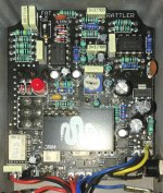
I had the opportunity to play my mate’s Rattler V2, and thought the boost was a very nice addition, once we’d taken it down from it’s default maximum. As far as I know it’s not been traced and I thought it might be a bit of fun to bread board a circuit that might give a close approximation of what they did. So I thought I’d start this thread to get some of my initial impressions down in writing and see if anything stands out to any of you, or suggestions on things to try.

I’m presuming all the SMD components at the bottom are for the switching, and that the through hole components are for the audio sections.
I’m guessing the RAT side of it is still very much a traditional RAT circuit, the main differences being that the tone control is a C100K (if it’s the same as the original rattler) so works in reverse compared to the filter control on a RAT. Symmetrical clipping with 1N4148s and asymmetric clipping with one 1N4148 and a red LED via a switch.
Their proprietary desecrate op amp development is interesting. JHS say the OP07 is effectively the same as the LM308, so I wonder why go to the trouble? Are they fearful that production of the OP07 is going to be discontinued in the near future? Or maybe it’s simple enough to do and adds a certain mystique to the product, I’m not planning on delving into that and will use an OP07.
The boost side I speculate is Boss SD1 inspired using asymmetric clipping with a fixed tone and output settings. The internal trim pot (105) is 1M so I think that is going to be in the feedback loop of the op amp rather than being an output level control. This suggests it is more about tone shaping and clipping than signal boosting.
There are a couple of things that I’ve noted but not worked through yet, if you are simply switching between two clipping options you only need a SPDT switch, but they have chosen a DPDT. Also, there appears to be a trace from one of the outside switch lugs to what looks like a ceramic capacitor, so would this form a low pass filter in the clipping section (the switch in that position would be for symetrical clipping)?
The second op amp might be being used as an input and output buffer for the boost instead of transistors as used in the SD 1.
Of course I could be, most likely am, completely wrong!
I’ve not built pedals or played around with breadboarding for a few years now and realised I missed it, so I want to get back into it, and to progress out of the painting by numbers phase and to have some notion as to what’s going on.
This will also me my first project using KiCad as I try and move away from the free version of Eagle.
If anyone has any thoughts or sees any errors in my assumptions so far, please let me know.


