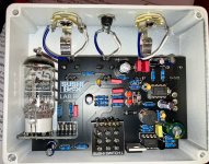
Lab Rat Gated on LED Setting

joelorigo

Well-known member
My Lab Rat is sounding gated as a note fades or is gently plucked on the LED clipping selection. It does not do it on the 1N4148 selection. Picking hard it seems normal. It did not do this previously. I don't see anything jumping out at me looking at the guts. Anyone have any suggestions on what the issue is?
 

Attachments

Last edited:
Suggestion/POV . . . . whenever I get stuck and micro-focused on one small part of circuit when troubleshooting, I will often change that micro-focus to look elsewhere for the problem. In your case, I'd start looking at the tube and the stuff going in & out of it.

But more to a more thorough troubleshooting approach, I don't see anywhere in this thread where all the supply voltages have been dbl-checked to ensure they are correct. Does the tube's heater voltage remain constant over time? Do the other voltage supplies remain constant over time?
Yeah, the supply voltages have never been checked. I it worked upon building it so assembling it wad the last thing I did before it started exhibiting this issue. How would one check supply voltages, and if the tube's heater voltage remain constant over time, and if the other voltage supplies remain constant over time? This would all be new to me?

EDIT: How does the fact that the SI diode setting seems to work properly fit in with the measurements of these?
 
Last edited:
Yeah, the supply voltages have never been checked. I it worked upon building it so assembling it wad the last thing I did before it started exhibiting this issue. How would one check supply voltages, and if the tube's heater voltage remain constant over time, and if the other voltage supplies remain constant over time? This would all be new to me?
To check for consistent voltage supply values over time, simple test them a moment or two after firing it up, (so everything as time to stabilize), then again after a few more minutes. Then continue to check the voltages every 5 minutes or so. If the heater voltage on the tube dips too low, that could cause the gating.

EDIT: How does the fact that the SI diode setting seems to work properly fit in with the measurements of these?
Consider how the Si diodes have a lower Fvd than the LEDs and how that difference will affect the signal going into the tube. If any of the tube's supply voltages are drifting, it could alter the performance of the tube and cause it to exhibit some sort of signal threshold difference (insufficient signal level?) between the diodes and LEDs.

Mostly, I'm suggesting that we not get hung up on the clipping section before the tube. If, however, expanded troubleshooting still takes you back to the clipping section, then I'd start looking very closely at the PCB for possible shorts or intermittent cracks/opens in any of the traces with some continuity testing while the unit is powered down.
 
To check for consistent voltage supply values over time, simple test them a moment or two after firing it up, (so everything as time to stabilize), then again after a few more minutes. Then continue to check the voltages every 5 minutes or so. If the heater voltage on the tube dips too low, that could cause the gating.
Yes thank you! When I asked about "checking supply voltages" and the tube's "heater voltage" I meant literally, lol. Where do I measure? I assume with the DMM. I started as building pedals with no soldering or electrical experience 6 years ago and even though I have learned a lot from this forum, I'm still just a step above "paint by numbers."

Consider how the Si diodes have a lower Fvd than the LEDs and how that difference will affect the signal going into the tube. If any of the tube's supply voltages are drifting, it could alter the performance of the tube and cause it to exhibit some sort of signal threshold difference (insufficient signal level?) between the diodes and LEDs.
Thanks for this also. It's great to get more of an understanding of what's going on in a circuit.

Mostly, I'm suggesting that we not get hung up on the clipping section before the tube. If, however, expanded troubleshooting still takes you back to the clipping section, then I'd start looking very closely at the PCB for possible shorts or intermittent cracks/opens in any of the traces with some continuity testing while the unit is powered down.
Sounds good! Now that you say this. Is it possible that the tube is the problem? The one I have in there is possibly one that was causing a problem in an amp and got mixed up in my (small) stash. I think I have another one could try.
 
Yes thank you! When I asked about "checking supply voltages" and the tube's "heater voltage" I meant literally, lol. Where do I measure? I assume with the DMM. I started as building pedals with no soldering or electrical experience 6 years ago and even though I have learned a lot from this forum, I'm still just a step above "paint by numbers."
From the schematic you've posted, look at the "VIN" point on the 12AX7, should be pins #4 & #5. I'd also verify that the 250v supply is there. (Pin #1 or #6.)
Sounds good! Now that you say this. Is it possible that the tube is the problem? The one I have in there is possibly one that was causing a problem in an amp and got mixed up in my (small) stash. I think I have another one could try.
Yeah. Easiest test would be to swap the tube.
 
Changing the tube didn’t fix the issue.

The DC jack has 9.13 and the cathode of the 1N5817 is 8.78. So that seems all normal,right?
Yeah. The Fvd (0.35V) of the 1N5817 accounts for the difference between the DC jack and after that diode.

What about the other voltages? (250v, VRef, etc . . . )
 
After replacing the tube and testing, I let it sit for an hour and I plugged in and got this:
Pin 1 - 151
Pin 2 - 0
Pin 4 - 0
Pin 6 - 239

Leaving it plugged in for about 5 minutes I got:
Pin 1 - 149
Pin 2 - 0
Pin 4 - 8
Pin 6 - 238

After another 5 minutes I got the same results
 
Looking over this again I realized I measured the wrong group of pins slightly. D’oh!
Here, let’s try this again:
Pin 1 - 147
Pin 4 - 0
Pin 5 - 8
Pin 6 - 242

After 5 minutes:
Pin 1 - 149
Pin 4 - 0
Pin 5 - 8
Pin 6 - 238
 
Looking over this again I realized I measured the wrong group of pins slightly. D’oh!
Here, let’s try this again:
Pin 1 - 147
Pin 4 - 0
Pin 5 - 8
Pin 6 - 242

After 5 minutes:
Pin 1 - 149
Pin 4 - 0
Pin 5 - 8
Pin 6 - 238
Those seem to be right in the ballpark. So now you've removed suspicion from power supply and the tube.

With the power on and no signal going into the circuit, what is the DC voltage at pin #2 of the tube?
Then, with the power on and a 1kHz @ 1.0v signal at the input, what is the DC voltage at pin #2 of the tube?
Then, with the power on and a 1kHz @ 1.0v signal at the input, what is the AC voltage at pin #2 of the tube?
Here, we're trying to learn if there is a DC component at the top of the clipping section (input to the tube) and what bearing a live signal has on the issue.

The next round of testing would involve signal tracing with a scope.
I have a tone generator app on my iPad that I can choose 1000Hz but I don’t see any adjustment options for voltage. Am I going get one that has that feature?

Also, I don’t have and have never used a signal generator. Are there apps or do I need hardware?
 
I have a tone generator app on my iPad that I can choose 1000Hz but I don’t see any adjustment options for voltage. Am I going get one that has that feature?

Also, I don’t have and have never used a signal generator. Are there apps or do I need hardware?
Tone generators on Apple devices typically output based on the device's volume control. Knowing the sig gen's voltage output will help verify what you read throughout the circuit's signal path when measuring. So you may want to measure the unloaded output of the iPad's signal generation so you know ahead of testing time what you're starting with.
 
Those seem to be right in the ballpark. So now you've removed suspicion from power supply and the tube.

With the power on and no signal going into the circuit, what is the DC voltage at pin #2 of the tube?
1.3
Then, with the power on and a 1kHz @ 1.0v signal at the input, what is the DC voltage at pin #2 of the tube?
Then, with the power on and a 1kHz @ 1.0v signal at the input, what is the AC voltage at pin #2 of the tube?
Maxing the volume on the iPad I only get less than a volt on the tip of the input jack so that’s not good. But here’s the DC and AC measurements on pin #2:
DC .83
AC 2.75
 
I think we’re over thinking this. It only sounds like this with the LEDs, and not the diodes? It kind of narrows it down to the switch or the LEDs. Can you take it out and jumper / bypass the LEDs and see if it still happens?
This would be removing the LEDs and toggle from the circuit, so just using the SI diodes? If it operates normally, as it does when selected to the SI diodes, it would localize the problem to the LEDs or toggle, or their current soldering, yes?
 
I am hesitating on this to think for a minute, Although I think I could handle sucking the solder out and removing the toggle switch I have never done one before. I have done pots which also use an abundance of solder. I know that more interventions increases the risk of damage to the PCB. And it works on the SI setting so do I just live with it and only use it on that setting? Opinions welcome.
 
Back
Top