Leprechaun Not working...Confuzzled

ProfSkibs

New member
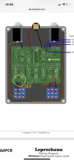
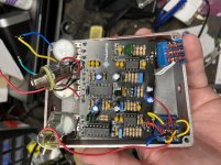
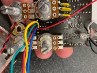
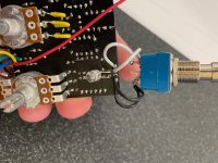
This is my second build. The first was a hummingbird/woodpecker. That works beautifully. So for a second I chose something more complex. I built the Leprechaun, and it doesn’t work. The wires all appear to be correct, going by the diagrams supplied by Pedal PCB. I had an expression jack in the original build- took it out to rule out the Jack as an issue. Jumped tip to switch like the diagram but never removed the other wires so I could replace the jack, maybe. Cant find any cold solders or bridges visually or under magnification. Power to both OP-AMPS seems okay I think. Had a power switch board on the original build. Took that out to rule it out. Hand soldered the switch back in.
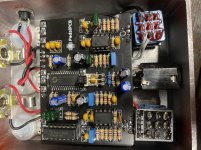
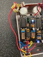
I hand soldered in an FV-1 from another supplier (pedalpcb was out of stock). I’m only a hobbyist and I don’t know how to troubleshoot this thing any further. Multimeter shows the Power from jack matches the power at the board terminals. Voltage regulator is showing 3.3ish volts after drop. Pots don’t seem to have voltage. Magic LED is always on. The power LED is always off. UNLESS I depress the switch and hold it. When engaged I get some dry guitar tone and a weak digital swirl...I have no idea what’s going on here. Having trouble getting good photos posted to boot! Please help me if you can
 

Attachments

  • 6EDCF66E-2F67-456B-83FE-6F169C426942.jpeg
    6EDCF66E-2F67-456B-83FE-6F169C426942.jpeg
    207.6 KB · Views: 28
  • 3664F985-4057-483B-BF57-6366F764DA63.jpeg
    3664F985-4057-483B-BF57-6366F764DA63.jpeg
    390.4 KB · Views: 29
  • 8BBEADD0-3C0A-42BE-B984-606600AA0BE6.jpeg
    8BBEADD0-3C0A-42BE-B984-606600AA0BE6.jpeg
    392.6 KB · Views: 28
The last time I used a non-standard pedal parts vendor for an FV-1chip, I got burned. Check the input and output of the FV-1 chip with an audio probe to rule out a bad FV-1. And with regard to your "The power LED is always off. UNLESS I depress the switch and hold it." issue, that suggests the switch is a momentary on. Use your DMM continuity to ensure it is a latching switch.

Also, is the expression jack a fully switched TRS style? That is a must for the expression jack.
So you helped me sort out one issue. Thanks. The switches were in fact momentary and not marked as such. I’m really hoping the FV1 is not bad...I used a vendor Im familiar with Amplified Parts. That would be seriously disappointing. Do you know is there a way to test an unmounted FV1?
 
no easy way for a hobbyist to test an unmounted fv-1, AFAIK.
in my experience you need to troubleshoot the other possible causes of board failure on an FV-1 pedal to eliminate things other than a bad FV-1 chip.

maybe others can spot something you might have missed on your build pics.

Here is an approach to try to isolate the problem and see if you might have a bad FV-1.

use your meter to check pins 3 and 6 on the fv-1 for power. you should be seeing about 3 volts there. use your meter to see if you have connections to ground on pins 7, 11 and 12 (you can use the schematic in the Arachnid build document for reference).

if you have power and ground on the FV-1, build an audio probe if you don't have one. easy to do with a 1/4 inch jack, capacitor, alligator clip and some wire. check the forums or do a google search.

with your audio probe and the effect powered on with an audio signal plugged into it, see if you have audio coming in and the "IN" pad on the pcb. if you do, check to see if you have audio coming in on pin 1 and/or pin 2 on the FV-1. If there is no audio coming in the problem will be somewhere on the board before it gets to the FV-1. If you have audio coming in on pins 1 and/or 2, check pin 28 to see if you have audio coming out of the FV-1. If you do, the problem is not the FV-1.

If you have power, ground, audio going in but not coming out --- you might have a bad chip.

that's the overview.
 
Thank you. I wasn't sure where to place the probes. I'm going to check things out with the meter later today. and I suspect I'll be making an audio probe this evening. As for the images I am attaching below. I dont see any cold solders, Ive metered a few random places here and there and Ive gotten power it seems across the board, but the pots were giving me trouble. Im in a bit over my head I guess. Best way to learn...I hope
 

Attachments

  • IMG_0691.jpg
    IMG_0691.jpg
    696 KB · Views: 9
  • IMG_0690.jpg
    IMG_0690.jpg
    651.5 KB · Views: 10
  • IMG_0689.jpg
    IMG_0689.jpg
    514.9 KB · Views: 9
  • IMG_0688.jpg
    IMG_0688.jpg
    758.7 KB · Views: 11
Back
Top Bottom