Leprechaun routing question

dross

New member
I’m building a Leprechaun and I’m planning on using two of these relay bypass switches to control it:https://mas-effects.square.site/pro...true&sa=false&sbp=false&q=false&category_id=5

My question is what would be the labels for the two sets of pads that connect the switches? I’m using the switch pcbs to control the LEDs, and it looks like two of the pads for the Regeneration switch do that, so which two pads would I use to just switch the Regeneration? I’m also planning the same for the other switch, so if you could answer the same question again? Thanks-? I really like the way your pcbs are layed out, btw

Don
 
I'm in the middle of attempting the same thing! I'm pretty new to this, but let me jot down my thoughts. Hopefully someone with more experience can chime in.

For the Bypass Switch:
- Connect the tip of the input jack to JI on the breakout board
- Connect the tip of the output jack to JO on the breakout board
- Connect the hole typically labelled "IN" on PedalPCB builds (the "left" hole in the group of four) to BI on the breakout board
- Connect the hole typically labelled "OUT" on PedalPCB builds (the "right" hole in the group of four) to BO on the breakout board

For the Regeneration switch:
- Connect one of the Regen connections to the BO on the breakout board
- Connect the other one to JO on the breakout board
- We're using BO and JO instead of BI and JI because BI is grounded when the switch is off
- Also probably leave out the optional TLP222G just to make sure JO doesn't accidentally get connected to ground

That leaves two questions:
- How to power the relay breakout boards?
- How to wire up the LEDs?

Here are my current thoughts:

To power the breakout boards, replace R100 and R101 with just a bit of wire. Then jumper the existing LED holes the same way. That way, the holes that are typically labelled on PedalPCB diagrams as "SW" (usually for connecting the LED to the switch) becomes a 9v supply line. Then use those 9v supply lines and the ground connections that are typically used to complete the LED circuit (the "middle two" holes in each group of four at the bottom of the main board) to power the relay breakout boards.

For the LEDs, connect the anodes to the "LED" holes of the breakout board. Then connect the cathode to a resistor (maybe something like 3k3 rather than original 4k7 since it's 5v instead of 9v?) and connect the other end of the resistor to ground, either by combining with the board ground or just by using the extra AG connection point.

I'll post a picture if I get it working.
 
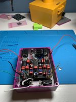
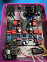
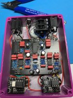
It works!!!

I did have the wires wrong at first. When looking into the back of the pedal, I believe the holes at the bottom are:

IN GND SW OUT GND SW IN OUT

It first I had IN and GND switched on the right side group. The trick of "converting" SW to +9v worked really well! The biggest trouble I had was that the anode lead from the LED wouldn't quite reach the breakout board. I'll have to add a little wire next time. I'm definitely going to build another one of these :)
 

Attachments

  • IMG_4120.JPG
    IMG_4120.JPG
    174 KB · Views: 25
  • IMG_4121.JPG
    IMG_4121.JPG
    282.8 KB · Views: 26
  • IMG_4123.JPG
    IMG_4123.JPG
    273.2 KB · Views: 25
Back
Top Bottom