I posted this in the workbench thread, and a few people wanted me to walkthrough my "super magic magic secrets to how I made this preamp and how I'm going to make more. Disclaimer: HIGH VOLTAGES HURT AND CAN KILL YOU. BE SAFE, YA GOOBERS. A few caveats:
1. I had access to 1U rack enclosures from old telecom equipment for distance education and conference rooms.
2. The channel PCBs were from Merlin Blencowe back when he had universal tube amplifier PCBs.
3. I've built a few guitar amps before, so I've had some experience "knowing what I'm doing"
4. Lots of access to old 12V 2A plus power supplies from old laptops, etc. at work.
Honestly, this project has been in the works for about 5 years, but has been on the backburner as I've gone through building guitars, back to pedals, and going forward with preamps. After small SMPS pcbs have become more common, it made this more attainable. I had already failed with a toroid transformer and two smaller PCB mount transfomers. So, failure aside, winter break and snow days have allowed me to tackle this project. Plates are lower than usual in most Marshall since there are 5 tubes on the SMPS power supply. But it sounds good, so I'm super happy.
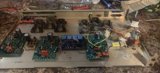
The 18watt channel is based on a Lite iiB revision of the 18watt (from mHuss and others at 18watt) using parallel triodes (on the right side with the eyelet board and two 1uF Wima caps). Not much gain but a nice light clean sound.
Middle channel is a Plexi with a M/N taper Bourns potentiometer (basically a mixer potentiometer) for the normal and bright channels. There's no clean at all on this: it's straight ahead early 70s rock. Thick Thin Lizzy 'Jailbreak'
Leftmost channel is a JCM800 with cathode bypass changes. All cathodes have 2k7/.68uF bypass except the cathode follower which has 56k instead of 100k. The 33k slope resistor on the tone stack has a 50k slope attached to it which controls the upper mids. This control works when you turn down the treble and slide the slope control so even as in gets a bit darker and less "shrill" you can make it cut through with the slope.
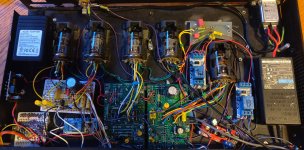
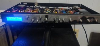
The LCD screen was from work, which I swapped with what was originally in there. I put an I2C cable on there to simplify the wiring to the Arduino. The Arduino controls the relays on the main volume pot to shunt the sound to ground. Just switching at the input and output caused bleed through on the channels. I don't have the footswitch buttons done yet: I have to switch it with a alligator clip to ground. The LCD will tell you what channel is on and which channel it is. Now, I didn't write the code, because I SUCK at coding. ChatGPT did it, and didn't do too bad.
I had to tackle oscillations on the JCM channel with grid stoppers and shielded cable. The Plexi input wire actually was picking up frequency chatter from the SMPS (wild), so I needed to add shielded wire. I had to pull the Arduino power supply from the filament DC brick, into a stepdown PCB board to 9Vish because the 6V from the SMPS board caused too much current draw on the Arduino and relays. There is no layout - I had to wing it and redo it a few times. The last problem I had was major buzzing, but that was because I needed to ground the relays to the chassis better.
There you go everyone. Any dingus can build it if you're safe and smart. I can answer questions if you have it and if you want the code, I'll send it to you. It's pretty simple and AI generated where I tweaked the pin numbering. Onward now to the 4 channel Fender and variants preamp (Tweed, BlackFace, Dumble, Mesa Boogie) with two SMPS boards for 200VDC on the plates. Thanks for listening to my rambling.
1. I had access to 1U rack enclosures from old telecom equipment for distance education and conference rooms.
2. The channel PCBs were from Merlin Blencowe back when he had universal tube amplifier PCBs.
3. I've built a few guitar amps before, so I've had some experience "knowing what I'm doing"
4. Lots of access to old 12V 2A plus power supplies from old laptops, etc. at work.
Honestly, this project has been in the works for about 5 years, but has been on the backburner as I've gone through building guitars, back to pedals, and going forward with preamps. After small SMPS pcbs have become more common, it made this more attainable. I had already failed with a toroid transformer and two smaller PCB mount transfomers. So, failure aside, winter break and snow days have allowed me to tackle this project. Plates are lower than usual in most Marshall since there are 5 tubes on the SMPS power supply. But it sounds good, so I'm super happy.
The 18watt channel is based on a Lite iiB revision of the 18watt (from mHuss and others at 18watt) using parallel triodes (on the right side with the eyelet board and two 1uF Wima caps). Not much gain but a nice light clean sound.
Middle channel is a Plexi with a M/N taper Bourns potentiometer (basically a mixer potentiometer) for the normal and bright channels. There's no clean at all on this: it's straight ahead early 70s rock. Thick Thin Lizzy 'Jailbreak'
Leftmost channel is a JCM800 with cathode bypass changes. All cathodes have 2k7/.68uF bypass except the cathode follower which has 56k instead of 100k. The 33k slope resistor on the tone stack has a 50k slope attached to it which controls the upper mids. This control works when you turn down the treble and slide the slope control so even as in gets a bit darker and less "shrill" you can make it cut through with the slope.
The LCD screen was from work, which I swapped with what was originally in there. I put an I2C cable on there to simplify the wiring to the Arduino. The Arduino controls the relays on the main volume pot to shunt the sound to ground. Just switching at the input and output caused bleed through on the channels. I don't have the footswitch buttons done yet: I have to switch it with a alligator clip to ground. The LCD will tell you what channel is on and which channel it is. Now, I didn't write the code, because I SUCK at coding. ChatGPT did it, and didn't do too bad.
I had to tackle oscillations on the JCM channel with grid stoppers and shielded cable. The Plexi input wire actually was picking up frequency chatter from the SMPS (wild), so I needed to add shielded wire. I had to pull the Arduino power supply from the filament DC brick, into a stepdown PCB board to 9Vish because the 6V from the SMPS board caused too much current draw on the Arduino and relays. There is no layout - I had to wing it and redo it a few times. The last problem I had was major buzzing, but that was because I needed to ground the relays to the chassis better.
There you go everyone. Any dingus can build it if you're safe and smart. I can answer questions if you have it and if you want the code, I'll send it to you. It's pretty simple and AI generated where I tweaked the pin numbering. Onward now to the 4 channel Fender and variants preamp (Tweed, BlackFace, Dumble, Mesa Boogie) with two SMPS boards for 200VDC on the plates. Thanks for listening to my rambling.
.gif")