digitalyeti
Member
Hey All,
Since I didn't see a build report for this pedal yet, I thought I would add one to maybe make life easier for the next person who comes along wanting to build this awesome circuit. This is an amazing pedal and I am so impressed and grateful that PedalPB figured out how to fit everything into a 125B enclosure. I love the original Low Tide, but never really wanted to give up that much space on my board. This mini version is the best of both worlds -- a huge thank you to making this board. Here are my notes:
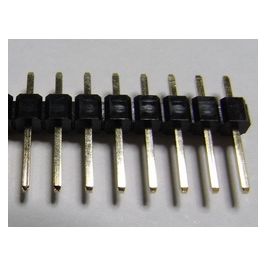
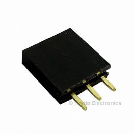
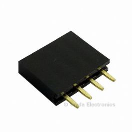
First of all, for those who don't know, this pedal is two boards that stack on top of each of each other. The two boards connect to each other via three sets of header pins. The only way I would know this is that I built a Sagan Delay a while back with the same setup. This brings me to my first and most important note. THIS IS A TIGHT FIT. When I say tight fit, I think I have less than a millimeter of clearance to get the back onto the pedal. If I had not dry fitted everything together before soldering the header pins and capacitors, this would not have fit together. As is, I had to rework and shorten my header connectors to give the extra few millimeters so all would fit. I also had to bend and side mount a lot of capacitors so everything fit. Honestly, not a huge issue, but I did do a lot of test fitting before soldering to make sure it would work. I actually think the boards are laid out really well -- all of the larger value capacitors were somewhere that gave them space be bent into place.
Even with that said, I still had some capacitors from the bottom board hitting the top board. What I did to fix this was make a thin sheet of electrical tape, by taping two pieces together so that the sticky side faced each other. I then cut this sheet to size and placed this sheet between the two boards to prevent shorts. I probably could have just covered the bottom of the top board with electrical tape, but I wanted something easy to remove if I needed to troubleshoot. Plus, if it was stuck to the board it would break down into a gooey mess in a few years. I was surprised how well my jury rigged solution worked.
I did make one idiot error in assembling. I socketed all the ICs and accidentally installed the ICs upside down on the top board. I have built so many PedalPCB boards that having a board without the customary layout threw me. I noticed this when the pedal did not work properly and then flipped the ICs around. What I did not know was that powering up the pedal with the ICs reversed killed the LM258. It was not hard to figure out because after being installed in the proper alignment the dead LM258 ran HOT. Like burning my finger hot. Once I swapped it out for a new one, the pedal fired right up and worked great.
I am happy that I built the original Low Tide because it takes a bit of practice to properly set the trimpots. Neither of the trimpots are hard to set, but on first try the pedal did not work -- I had to adjust the BBD trim first for it to work. If I did not know this was necessary, I might have gone far down the troubleshooting rabbit hole before I touched the trimpot. So if you are building this and it does not work on first try -- make sure to play with the trimpots before desoldering anything.
For those of you looking for parts I was able to find the A1M dual from LoveMySwitches. I could not find any V3207Ds. However, I could find some MN3207s. What I actually did was pull a V3207D from a Caesar build I had and replace it in the Caesar with the MN3207. I think I got the MN3207s from GuitarPCB a little while ago. That was also where I got some through hole J201s.
Anyway, I just wanted to post to pay back you all for the good info you have given me over the last few years. I usually lurk and anything I would share has already been shared. However, since this is a new build, I thought I would give my experience and maybe save somebody some heartache. Attached are some photos, if you are interested:


Since I didn't see a build report for this pedal yet, I thought I would add one to maybe make life easier for the next person who comes along wanting to build this awesome circuit. This is an amazing pedal and I am so impressed and grateful that PedalPB figured out how to fit everything into a 125B enclosure. I love the original Low Tide, but never really wanted to give up that much space on my board. This mini version is the best of both worlds -- a huge thank you to making this board. Here are my notes:
First of all, for those who don't know, this pedal is two boards that stack on top of each of each other. The two boards connect to each other via three sets of header pins. The only way I would know this is that I built a Sagan Delay a while back with the same setup. This brings me to my first and most important note. THIS IS A TIGHT FIT. When I say tight fit, I think I have less than a millimeter of clearance to get the back onto the pedal. If I had not dry fitted everything together before soldering the header pins and capacitors, this would not have fit together. As is, I had to rework and shorten my header connectors to give the extra few millimeters so all would fit. I also had to bend and side mount a lot of capacitors so everything fit. Honestly, not a huge issue, but I did do a lot of test fitting before soldering to make sure it would work. I actually think the boards are laid out really well -- all of the larger value capacitors were somewhere that gave them space be bent into place.
Even with that said, I still had some capacitors from the bottom board hitting the top board. What I did to fix this was make a thin sheet of electrical tape, by taping two pieces together so that the sticky side faced each other. I then cut this sheet to size and placed this sheet between the two boards to prevent shorts. I probably could have just covered the bottom of the top board with electrical tape, but I wanted something easy to remove if I needed to troubleshoot. Plus, if it was stuck to the board it would break down into a gooey mess in a few years. I was surprised how well my jury rigged solution worked.
I did make one idiot error in assembling. I socketed all the ICs and accidentally installed the ICs upside down on the top board. I have built so many PedalPCB boards that having a board without the customary layout threw me. I noticed this when the pedal did not work properly and then flipped the ICs around. What I did not know was that powering up the pedal with the ICs reversed killed the LM258. It was not hard to figure out because after being installed in the proper alignment the dead LM258 ran HOT. Like burning my finger hot. Once I swapped it out for a new one, the pedal fired right up and worked great.
I am happy that I built the original Low Tide because it takes a bit of practice to properly set the trimpots. Neither of the trimpots are hard to set, but on first try the pedal did not work -- I had to adjust the BBD trim first for it to work. If I did not know this was necessary, I might have gone far down the troubleshooting rabbit hole before I touched the trimpot. So if you are building this and it does not work on first try -- make sure to play with the trimpots before desoldering anything.
For those of you looking for parts I was able to find the A1M dual from LoveMySwitches. I could not find any V3207Ds. However, I could find some MN3207s. What I actually did was pull a V3207D from a Caesar build I had and replace it in the Caesar with the MN3207. I think I got the MN3207s from GuitarPCB a little while ago. That was also where I got some through hole J201s.
Anyway, I just wanted to post to pay back you all for the good info you have given me over the last few years. I usually lurk and anything I would share has already been shared. However, since this is a new build, I thought I would give my experience and maybe save somebody some heartache. Attached are some photos, if you are interested: