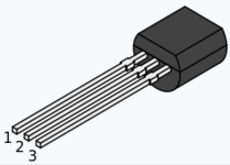
SOLVED Mofeta Build Normal Channel not working + more

ZoraAD

New member
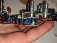
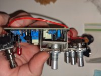
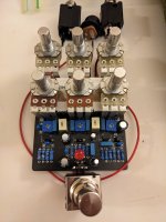
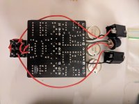
Hey all! This is my first post here, so if I missed any rules please let me know. Not new to pedal builds however which makes the mistake I made in this build more embarrassing, haha. I put the pots on the wrong side of the board, so they work in reverse. Well, not all the pots work in reverse. The bass and treble knobs work the correct way, which doesn't make sense to me. I've pulled the pots and am going to order some short leg pots to put on the correct side, but before I do I want to make sure that there are no other obvious issues to correct in the meantime. And yes, I did wire the switch correctly when I had the board in reverse, then when I pulled the pots and flipped the board I re-wired it.

Also, the normal channel doesnt seem to work. Master all the way up, bright channel all the way down, normal volume does nothing.

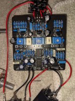
Polarized components seem to be in the correct way and none of the soldering looks dodgy to my eye on a first pass. Any guidance y'all can give would be appreciated!

Images before and after I pulled the pots out below: PXL_20240319_041325669.MP.jpg PXL_20240319_041351999.MP.jpg PXL_20240319_041407880.jpg PXL_20240319_041418169.jpg PXL_20240319_045120262.jpg
 
Solution
Hey there, @ZoraAD. I'd wait until you get the potentiometers replaced and installed in the correct orientation before jumping to conclusions that something is broken.

If the board still fails to work after you install the potentiometers correctly, you might start troubleshooting by double-checking your voltages.

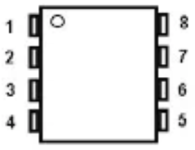
Check the voltages at pins 1-8 on IC100 and IC1.
1710876974565.png

This board uses four JFETs, Q1-Q4, three of them have bias trim pots, BIAS 1- BIAS 3. Do you recall what you biased those trim pots to after assembling? I don't see listed specs for setting those trim pots in the build docs, but generally speaking, you'd bias those to half of supply. In this case, supply is +18V. You'd measure this by placing your DMM...
Hey there, @ZoraAD. I'd wait until you get the potentiometers replaced and installed in the correct orientation before jumping to conclusions that something is broken.

If the board still fails to work after you install the potentiometers correctly, you might start troubleshooting by double-checking your voltages.

Check the voltages at pins 1-8 on IC100 and IC1.
1710876974565.png

This board uses four JFETs, Q1-Q4, three of them have bias trim pots, BIAS 1- BIAS 3. Do you recall what you biased those trim pots to after assembling? I don't see listed specs for setting those trim pots in the build docs, but generally speaking, you'd bias those to half of supply. In this case, supply is +18V. You'd measure this by placing your DMM negative lead to ground and the positive lead to the Drain pin of each of the biased JFETs. Drain pin on a typical 2N5457 is pin 1.
1710877261650.png

Write all of these voltages down for follow-up posts here, that'll likely be the first question that's asked.
 
Solution
Hey there, @ZoraAD. I'd wait until you get the potentiometers replaced and installed in the correct orientation before jumping to conclusions that something is broken.

If the board still fails to work after you install the potentiometers correctly, you might start troubleshooting by double-checking your voltages.

Check the voltages at pins 1-8 on IC100 and IC1.
View attachment 71055

This board uses four JFETs, Q1-Q4, three of them have bias trim pots, BIAS 1- BIAS 3. Do you recall what you biased those trim pots to after assembling? I don't see listed specs for setting those trim pots in the build docs, but generally speaking, you'd bias those to half of supply. In this case, supply is +18V. You'd measure this by placing your DMM negative lead to ground and the positive lead to the Drain pin of each of the biased JFETs. Drain pin on a typical 2N5457 is pin 1.
View attachment 71056

Write all of these voltages down for follow-up posts here, that'll likely be the first question that's asked.
Thanks for the reply Brett! I did nominally bias the transistors to 9v, and then tweaked them around to see if that would alleviate the issue with the normal channel. As soon as the new pots come in I will measure the voltages of the IC as you've suggested.
 
Back
Top