MBP SludgeHammer Not Working

8stringalchemy

New member
UPDATE 1: Works just fine now. Working on figuring out what to do with the CHS1 pad.

UPDATE 2: Got everything sorted. Thanks everyone!

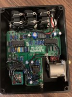
Not a PedalPCB build but I need some help troubleshooting. The MBP Sludgehammer that I just finished isn't working. It doesn't even turn on and the direct jack has no output. No idea what's going on. I'd appreciate any help I can get.
IMG_0205.jpg
 
Last edited:
Can you provide a clearer picture of the foot switch and verify your wiring throughout (i.e., ensure the correct connections are being made to the right places and the wire has good integrity).

What’s going on with the XLR jack? If you don’t use the CHS1 pad, the ground lift won’t do anything.

EDIT: Also ensure that the chassis ground connection is making good contact with the enclosure. It looks like there’s powder coat where it needs to be bare metal.
I've identified an issue with the wiring of the jacks that I'm planning on fixing tomorrow (they're designed to act as switches so the pins I wired up are disconnected when the cable is plugged in). I also sanded off a patch of the powder coat so the spring can make contact. As for the XLR jack, I don't really know where the CHS1 pad is supposed to connect since the XLR has no chassis pin. Should I just solder a wire to the side of the jack? Also, would any of these issues cause the LED to not light? I'll post an update once I've had a chance to work on it.

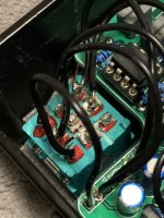
In the meantime, here's a closeup of the footswitch (it's a bit of a mess, It was involved in a failed desoldering job, but I can guarantee that it works). Everything is wired correctly as far as I can tell and I've measured the wires/switch with a multimeter.
IMG_0206.jpg
 
Last edited:
Can you provide a clearer picture of the foot switch and verify your wiring throughout (i.e., ensure the correct connections are being made to the right places and the wire has good integrity).

What’s going on with the XLR jack? If you don’t use the CHS1 pad, the ground lift won’t do anything.

EDIT: Also ensure that the chassis ground connection is making good contact with the enclosure. It looks like there’s powder coat where it needs to be bare metal.
Update. I got everything to work and it turns out the LED is wired backwards. I gotta figure out how to fix that. Still confused about what to do with the CHS1 pad.
 
Good catch with the LED.

Can you find a datasheet for the XLR jack? That would give an indication of the chassis connection.

I don’t entirely follow what’s going on with your jacks. How are you deviating from the build instructions?

Note that this is not a true bypass effect. The DIRECT OUT is not taken from the input and passes through the first part of the circuit.
This is the best schematic I can find: https://www.mouser.com/ProductDetai...MI4JL0hovG_AIVlonICh1BfgubEAAYASAAEgIO6fD_BwE
 
I noticed that, but I can't find what that "G" pin corresponds to. I can only see the 3 that I wired up.
It might be that you're using a 3 pin XLR socket. I found that the 4 pin version accommodates all of the PCB wires. Maybe worth trying to wire the ground pad on the PCB direct to the bolt that secures the XLR to the chassis. Then you'll have an improvised chassis ground and all of the PCB's XLR options accounted for.

But this seems well downstream of the actual problem of no sound. I'd start by checking that you've got the signal and ground wires to the jacks correct, which is a bit hard to see from here. Ground is nearer to the chassis and signal in and out closer to the board if that makes sense.
 
Did you link the right part number? That's a PCB-mount part and should have a fourth lead coming from the middle of the back of the jack. On solder lug parts, there's typically an additional lug that looks different than the rest.

But this seems well downstream of the actual problem of no sound. I'd start by checking that you've got the signal and ground wires to the jacks correct, which is a bit hard to see from here. Ground is nearer to the chassis and signal in and out closer to the board if that makes sense.
Certainly is. I just wanted to tackle all the issues. I still don't understand what is going on with the isolated jack wiring. It sounds like the signal wires were soldered to the switching lugs. Yep, everything is soldered to the switched terminals.
 
Last edited:
Did you link the right part number? That's a PCB-mount part and should have a fourth lead coming from the middle of the back of the jack. On solder lug parts, there's typically an additional lug that looks different than the rest.


Certainly is. I just wanted to tackle all the issues. I still don't understand what is going on with the isolated jack wiring. It sounds like the signal wires were soldered to the switching lugs. Yep, everything is soldered to the switched terminals.
Might be time to try audio probing the circuit to see where you get signal and where not. I sometimes still miswire those switching jacks so that plugging the jack in actually disconnects audio. They're quite confusing at times.

One quick check would be to see if you get signal from the input and direct out jacks for starters. Sorry, I checked and noted that you don't get output from the direct out. I suspect that your jack wiring might need revising...
 
Last edited:
It might be that you're using a 3 pin XLR socket. I found that the 4 pin version accommodates all of the PCB wires. Maybe worth trying to wire the ground pad on the PCB direct to the bolt that secures the XLR to the chassis. Then you'll have an improvised chassis ground and all of the PCB's XLR options accounted for.

But this seems well downstream of the actual problem of no sound. I'd start by checking that you've got the signal and ground wires to the jacks correct, which is a bit hard to see from here. Ground is nearer to the chassis and signal in and out closer to the board if that makes sense.
The problem has been solved. Works just fine now. I can wire the pad to the bolt, but I've measured the resistance from the XLR to the spring and it is zero - shouldn't that serve the same purpose?
 
The problem has been solved. Works just fine now. I can wire the pad to the bolt, but I've measured the resistance from the XLR to the spring and it is zero - shouldn't that serve the same purpose?
Perhaps so, but what if you want the option to lift the ground in case of hum and so on?
 
So, basically I can wire the CHS1 pad to any part of the box and it'll work...
Yes. If I understand the BD correctly, the 4-pin XLR provides for connections to chassis ground as well as circuit ground for the ground lift function to work. The spring provides this by connecting directly to the metal of the enclosure. So what we’re doing is finding a workaround for your 3-pin socket by connecting the CHS1 pad to the chassis.
 
Yes. If I understand the BD correctly, the 4-pin XLR provides for connections to chassis ground as well as circuit ground for the ground lift function to work. The spring provides this by connecting directly to the metal of the enclosure. So what we’re doing is finding a workaround for your 3-pin socket by connecting the CHS1 pad to the chassis.
Makes sense. Thank you so much!
 
Back
Top