You are using an out of date browser. It may not display this or other websites correctly.
You should upgrade or use an alternative browser.
You should upgrade or use an alternative browser.
Mean Green Metal Machine led's?
- Thread starter EZS
- Start date
i think equinox has traced the good schematic , i have look and think it is ok from the trace i see
for this pcb : https://www.pedalpcb.com/wp-content/uploads/2022/08/MGMM.png
i have rename some component to corespondind to the schematic
for this pcb : https://www.pedalpcb.com/wp-content/uploads/2022/08/MGMM.png
i have rename some component to corespondind to the schematic

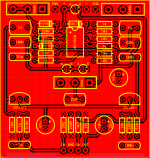
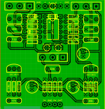
Thanks for checking. Attached is the PCB and front and back traces (unverified).i think equinox has traced the good schematic , i have look and think it is ok from the trace i see
for this pcb : https://www.pedalpcb.com/wp-content/uploads/2022/08/MGMM.png
i have rename some component to corespondind to the schematicView attachment 33818
Attachments
I wish some gut shot of the actual pedal(s) show up. So, is the 4558 single or a stacked chip setup??
I guess could just try it and see the difference, but would like to know stock how Mike did it.
Funny, I was thinking "Mean Green Machine" was for the TS-9. The PedalPCB page actually shows it's for the 808! I though the 808 had a second set of LEDs or soemthing?!?
Again, would help if we had gut shots of both the TS-9 and 808 Fortin versions and SEE the differences. Anyone know if these were gooped or not?
Robert
Reverse Engineer
Are we tracing a pedalpcb pcb? It's come full circle.
That's it, starting Nov 1 all PedalPCB boards will be gooped before shipping.
I wish some gut shot of the actual pedal(s) show up. So, is the 4558 single or a stacked chip setup??
I'll open it up and take some pics for you, it's really quite disturbing how sloppy the mod is.
No stacked ICs, they just swapped the four components on the board, changed the clipping diodes to LEDs, and then tacked the added 1N4148's and 220K resistor in "flying" fashion on the wire going to the Drive pot. They're just flopping around in there, very amateur-like.
And yes, consider your schematic confirmed.
")
Cybercow
Well-known member
I built one some months ago. Build report for my Little Green Mean Machine is here . . . .Anyone built this?
When the pedal is engaged/led on, I get no sound at all.
Feral Feline
Well-known member
Try diffused green LEDs instead of red, for more headroom before onset of clipping.
Also/or try 1 red & 1 green.
Also/or try 1 red & 1 green.
I think I used two 3mm clear (red) with a low current of only 1mA or 2mA. Not even 20mA like most common LEDs.Try diffused green LEDs instead of red, for more headroom before onset of clipping.
Also/or try 1 red & 1 green.
Feral Feline
Well-known member
I'm not sure how amperage affects the clipping; everything I've read about diodes clipping is about forward-voltage.I think I used two 3mm clear (red) with a low current of only 1mA or 2mA. Not even 20mA like most common LEDs.
Taken from a random web-search:
A "volt" is a unit of electric potential, also known as electromotive force, and represents "the potential difference between two points of a conducting wire carrying a constant current of 1 ampere.
Way-back-when I read that diffused had a different FV than clear, but that was debunked here:
Diffuse or Crystal Clear LEDs in Distortion Pedals?
Preemptively let me say I think I already know the answer, because every diode-based distortion pedal I own, or build photo I see here/elsewhere uses the DIFFUSE ones. ...BUT... As I understand it, the diffuse LEDs are all just white LEDs with colored plastic housings. So if that’s the case...
Interesting read.I'm not sure how amperage affects the clipping; everything I've read about diodes clipping is about forward-voltage.
Taken from a random web-search:
A "volt" is a unit of electric potential, also known as electromotive force, and represents "the potential difference between two points of a conducting wire carrying a constant current of 1 ampere.
Way-back-when I read that diffused had a different FV than clear, but that was debunked here:
Diffuse or Crystal Clear LEDs in Distortion Pedals?
Preemptively let me say I think I already know the answer, because every diode-based distortion pedal I own, or build photo I see here/elsewhere uses the DIFFUSE ones. ...BUT... As I understand it, the diffuse LEDs are all just white LEDs with colored plastic housings. So if that’s the case...forum.pedalpcb.com
I got those clear LEDs from mouser, spec'd 1mA with a forward voltage of 1.6v
Now truth be told when I switch it on, the LEDs don't light up not even a little bit. Bypass works fine, but as I said before, when it's switched on you can only hear the drive hissing as you max it (as if the guitar vol knob was rolled off completely)
I bought a bunch of 3mm diffused greens and reds earlier today, the guy said they're rated for running "3v through them like most LEDs" (his words, not mine) but they're chinesiums; we'll see tomorrow

Similar threads
- Replies
- 0
- Views
- 198
- Replies
- 7
- Views
- 1K
- Replies
- 3
- Views
- 300
- Replies
- 0
- Views
- 68