You are using an out of date browser. It may not display this or other websites correctly.
You should upgrade or use an alternative browser.
You should upgrade or use an alternative browser.
Median Compressor not working
- Thread starter huntest
- Start date
Erik S
Well-known member
Take some pictures and post them here.I built the Median Compressor and it doesn't work.
LED lights up but with no pedal or ,guitar sound of any kind.
LED goes out when switch is pressed and bypass works but with guitar sound only
I would appreciate any advice on what to check out to get this working.
Thanks
General advice - first check all the wires are going to the right places. If you’re lighting the LED and getting bypass signal, you did at least most of that right.
Second, go through and verify each part on the board. Use the color codes on the resistors to figure out the values and compare them to the build doc. Then do the same with the codes on the capacitors.
Third get a magnifier out and inspect all the solder joints reflow any that don’t look nice and check for bridges between joints.
Those are also the things we’ll be looking at/ for in your pictures, so pictures that are clear enough to see all the color codes is helpful.
Robert
George Cloney
Posting these for @huntest (You have to reply here, not to the emails from the forum)
I assume your bottom row of pots has dust covers like the top? Have you tried adjusting the trim pot?
I'm suspicious of your TL072s, but I'm not sure I've ever bought ST brand before so they might be OK.
More importantly, where did you get those through-hole 2N5457's?

I assume your bottom row of pots has dust covers like the top? Have you tried adjusting the trim pot?
I'm suspicious of your TL072s, but I'm not sure I've ever bought ST brand before so they might be OK.
More importantly, where did you get those through-hole 2N5457's?


Feral Feline
Well-known member
Here's a simple one to check...
Any substitutions?
With the pedal open and upside down, it's not unheard of to accidentally plug INTO the OUT and OUT-OF the IN...
Any substitutions?
Ex: A transistor-sub that's the reverse or non-stock pinout.
huntest
New member
Posting these for @huntest (You have to reply here, not to the emails from the forum)
I assume your bottom row of pots has dust covers like the top? Have you tried adjusting the trim pot?
I'm suspicious of your TL072s, but I'm not sure I've ever bought ST brand before so they might be OK.
More importantly, where did you get those through-hole 2N5457's?
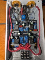
View attachment 111167View attachment 111168
Adjusting the trim pot did not make a difference.Posting these for @huntest (You have to reply here, not to the emails from the forum)
I assume your bottom row of pots has dust covers like the top? Have you tried adjusting the trim pot?
I'm suspicious of your TL072s, but I'm not sure I've ever bought ST brand before so they might be OK.
More importantly, where did you get those through-hole 2N5457's?
View attachment 111167View attachment 111168
I got all parts from Tayda
Thanks
Check that R102 is 10k, should be brown, black, black, red, brown like the resistors beside it. I see gold in the pic, but it might just be appearing that way in the picture.
Also check that the DC socket isn't wired backward. It looks like the black ground cable is wired to the upper lug and the red + cable is wired to the left lug, which according to the first picture would be + and - respectively.
The big DC jack lug is ground. The lug clockwise from that is +.
If you put the red probe of your DMM to + on the PCB and the black probe to - it should show 9V. If it shows -9V the DC jack is reversed.
Erik S
Well-known member
I spot checked a few resistors and didn’t find any errors other than the possible one @micmac noted above.
I was thrown by these initially, but it looks like you bought some .1% tolerance resistors with a purple band at the end? I had to check Tayda - I didn’t even know they sold those! I always get the 1% ones with the brown band from the “easy ordering page” then I line them all up the same way to make my troubleshooting easier.

Can’t see what’s going on under the cloth but a bridge there could get you in trouble.
I might give those switch lugs a reflow too. They all look connected from this angle, but I’d be more confident in them if they looked more like the top middle lug.

That’s an example of a solder joint that could use a closer inspection / reflow. It’s possible that ball of solder could be hanging on that pin but not contacting the pcb pad.

Not sure what’s going on there. I would expect to see some of the pins coming through.

Once you’re confident all the part values and wire/ jack connections are correct - if you want to do a real solder inspection you’ll want to pull the pcb and check the other side. Based on some of the cold looking joints on this side and very little solder flowing through, you could have some issues there.

jimilee
Well-known member
Wow. They’re priced like they’re real.
huntest
New member
I checked the IC voltages 1thru 8
Ic1 7.26,7.26,6.58,.000,7.24,7.28,7.24,7.77
Ic2 7.28,6.68,various,.0007,.25,7.25,7.25,7.77
Ic3 7.27,7.27,7.25,.000,.007,7.25,7.25,7.77
Ic4 7.21,7.24,7.22,6.12,5.62,5.68,7.13,7.77
Okay??
Also get a faint fluttering noise when I turn trim pot and when I touch the poles on the stomp switch
Ic1 7.26,7.26,6.58,.000,7.24,7.28,7.24,7.77
Ic2 7.28,6.68,various,.0007,.25,7.25,7.25,7.77
Ic3 7.27,7.27,7.25,.000,.007,7.25,7.25,7.77
Ic4 7.21,7.24,7.22,6.12,5.62,5.68,7.13,7.77
Okay??
Also get a faint fluttering noise when I turn trim pot and when I touch the poles on the stomp switch
z2amiller
Active member
Agree you need to check R101 and R102. The numbers on your ICs tell me that your VREF is totally wrong.
Am I reading correctly in the list above that the voltage on IC3.2 pin 5 is 0.007? That's exactly what you'd
expect if R102 was 10R instead of 10K (@micmac spotted this in #10).
(7.7 * 10 / 10,000 + 10) = 0.007
Your positive voltage is pretty low, too (7.77V), what do you measure coming directly out of your
power supply? Maybe the 10R in your voltage divider is causing the voltage drop, though, so
fix that first.
Is IC4 pin 4 really 6.something volts? That's supposed to be ground.
IMO you probably have a short to ground somewhere, too, if that's the case. That might also explain
the 7.77V on your supply voltage.
z2amiller
Active member
What is VREF? Anyway to check the ICs in or off the board?
re:VREF
An audio signal swings both positive and negative voltage relative to ground.
An op-amp can't amplify a voltage below the negative supply or above the positive supply.
Most op-amps in guitar pedals have a negative supply of GND (0V) and a positive supply of ~9V.
So pedals will supply a VREF voltage that is usually 1/2 of the input voltage by using a voltage
divider with two of the same-value resistors. R101 and R102 in this circuit create the voltage
divider in this circuit.
By referencing the incoming signal to 1/2 of the incoming voltage, the op-amp can amplify it in the
negative direction but still have that voltage be higher than the negative supply (which
is zero, GND). So for example, you reference your incoming guitar signal to 4.5V, you can amplify it to peaks
of +/- 4 volts or so, from 0.5 volts at the low points to 8.5 volts at the high points. In the median compressor,
R14 is an example of this, it "pulls up" the incoming guitar signal to VREF via a 1M resistor right before
the op-amp input. Then at the output of the op-amp, you use a capacitor to remove the
VREF offset - if you look at the schematic you can spot this pattern very clearly at IC2.1 and IC3.1.
If you didn't reference the incoming voltage to VREF and tried to amplify it by the same +/- 4V, the high
peaks would go up to 4V, but the negative peaks would stay at 0V, so you'd have only half of the
signal.
Some amps/pedals use charge pumps or transformers to give the op-amps a negative supply that is
negative relative to ground so there's no VREF needed, but that just trades one kind of complexity for
another.
The formula for calculating a resistor divider is (Vin * R2) / (R1 + R2) = Vout so if R101 and R102 are
both 10K you'd get (7.7V * 10K) / (10K + 10K) = 3.85V. In your case if R102 was 10R you'd get
(7.7V * 10) / (10K + 10) = 0.007V.
re: testing the ICs.
If you pull them and things measure way different, you can try moving stuff around or working by
the process of elimination. (But fix R102 first) If you have another guitar pedal somewhere that
is socketed, you can swap in the ICs. Dual op-amps all have the same pinout so they're swappable.