You are using an out of date browser. It may not display this or other websites correctly.
You should upgrade or use an alternative browser.
You should upgrade or use an alternative browser.
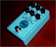
Median Compressor
- Thread starter music6000
- Start date
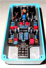
One thing to note when building this is when it comes time to Solder the Pots in, I found it was easier to Solder the Level & Compress Pot middle legs & then remove the PCB & Solder legs 1 & 3 from the back side of the Board as it is very tight with Electrolytics & MKT caps on the Component side.
Zennmaster
Well-known member
Lovely build!
I've generally moved on to soldering pots from the back whenever possible. It just seems cleaner overall, and if it looks like a good joint from the component side, then you can be pretty sure it's solid.
I've generally moved on to soldering pots from the back whenever possible. It just seems cleaner overall, and if it looks like a good joint from the component side, then you can be pretty sure it's solid.
Last edited:
chris.knudson
Well-known member
I love the color and the graphics. Very clean build as well.
1.8 volts on Drain of Q1, a furry Bird told me!Can anyone give a rookie some insight on how to set the bias on this pedal?
If you Crank it fully Clockwise it turns into a Distortion pedal,
andrewsrea
Member
I'll start with my cliche advice: 'If it sounds good, it is good!' So, use your ears as the final test.Can anyone give a rookie some insight on how to set the bias on this pedal?
To start, socket the 2N5457 FETs, as there is a chance you will replace them until you achieve an in-tolerance match.
With no signal and all knobs off to reduce self-noise, I recommend shooting for an average of -1.5v of Q1 & Q2, accepting up to a 10% tolerance (-1.35v to -1.65) between Pin #2 & Pin #3 (Vgss). If you get a positive voltage, you just have your DMM probes reversed, and absolute values will suffice (no need to panic).
Example: if Q1 measures -1.4v and Q2 -1.6v, you are ready to enjoy the effect.
I would personally follow up with sending a 1Khz sine wave signal into the pedal, and watch for linearity (top and bottom of the wave have equal voltage) and crossover distortion (a 'shelf' or dead spot which occurs in the middle reference point of the wave).
Here is my rationale:
- The trim appears to tuning both 2N5457 FETs which are operating in reverse polarity to each other (so that the compression occurs on both halves of the signal wave). So, any adjustment will be 'best compromise' between the two, and averaging is a good approach.
- The schematic suggests with no signal the voltage measurement between Pin#3 Gate & Pin #2 Source (Vgs) is -1.43v for Q1 and -1.5v for Q2. Looking at the schematic, this looks like what the reverse engineer measured and that the differences are the 2N5457's were close enough, but not perfectly matched. I surmise the original design was shooting for -1.5v, depending on the FETs Wampler was consistently sourcing (it is a memorable target spec a company can communicate to their supplier for acceptance and rejection, or vice versa).
- The more out of tolerance the FETs are to each other, the higher likelihood of crossover distortion (sounds harsh) at lower gain and compression settings. >10% difference between Q1 & Q2, I would audition 2N5457's until I achieved a closer match. The reverse engineer specs is about a 5% difference, which IMHO is great considering today's FETs. 2% is the best I've personally seen.
Hope this helps!
Last edited:
sticky1138
Well-known member
Which ICs did you use?
I spoke with Texas Instruments & LM833N was the closest match to the SMD version required.
Robert used TL072's while he was waiting for the SMD recommended & it works so most common dual OpAmp's will work.???
The other thing is the Blend control gives you more Compression as you turn it Clockwise so full compression is on 10 with the Compression knob on 10!
I love it!!!
Robert used TL072's while he was waiting for the SMD recommended & it works so most common dual OpAmp's will work.???
The other thing is the Blend control gives you more Compression as you turn it Clockwise so full compression is on 10 with the Compression knob on 10!
I love it!!!
sticky1138
Well-known member
Good to hear! I used TL072s in mine and love this compressor as well. Just wanted to confirm there is no dire reason to use those found in the original.
andrewsrea
Member
If it sounds good, it is good!Good to hear! I used TL072s in mine and love this compressor as well. Just wanted to confirm there is no dire reason to use those found in the original.
The design's OPA1678 (FET based) is faster, has a slightly lower input impedance (both better for processing transients) and has a lower noise floor, which makes it closer to use as a studio compressor as well as an instrument compressor. That said, TL072 (also FET based) has an impressive low noise floor and fast slew rate, compared to many ICs used in guitar pedals as well as sought-after studio gear from the late 70's and 80's.
Fretless
Member
Possibly the OPA1678 (mosfet) was used due its speed (and to be fair, might be difficult to hear as opposed to testing with a scope to notice any differences, making it sound as tho it’s doing the same thing). To me, a TL072 (jfet) seems less likely to be sterile sounding vs a mosfet based device.
Not sure if that’s the case here or not. Or for that matter what components were used in something like an 1176. Too many rabbit holes
Not sure if that’s the case here or not. Or for that matter what components were used in something like an 1176. Too many rabbit holes
andrewsrea
Member
Or for that matter what components were used in something like an 1176.
I recall a couple of TL071 (single op amps), a BF245 FET, and a bunch of discrete T0-92 discrete bi-polar transistors were in the UREI 1176's. So, a TL072 is appropriate. And I agree that in some effects, fast slew rate = sterile sounding. For instance, in a Rat I like a slow and messy LM308 and for a Timmy type circuit, I prefer a LM1458 that somewhat smears the sound.
Last edited:
Fretless
Member
Great point, it could make the attacks on notes harder. I was thinking more in terms of the way they saturate, or in the case of cmos/mosfet don’t saturate, but instead clip in a hard not so musical way. Or at least I believe that’s what they would do.… I agree that in some effects, fast slew rate = sterile sounding.…
This is just my basic understanding and interpretation, so I could be completely wrong about it. I don’t really know all that much about electronics, and the stuff I did learn I’ve mostly forgotten at this point, so my comments should have that disclaimer attached lol
Thanks for the info about the 1176!
Fact: The Wampler Ego 76 has the Trimmer set at 1.8v on the Drain of Q1!I'll start with my cliche advice: 'If it sounds good, it is good!' So, use your ears as the final test.
To start, socket the 2N5457 FETs, as there is a chance you will replace them until you achieve an in-tolerance match.
With no signal and all knobs off to reduce self-noise, I recommend shooting for an average of -1.5v of Q1 & Q2, accepting up to a 10% tolerance (-1.35v to -1.65) between Pin #2 & Pin #3 (Vgss). If you get a positive voltage, you just have your DMM probes reversed, and absolute values will suffice (no need to panic).
Example: if Q1 measures -1.4v and Q2 -1.6v, you are ready to enjoy the effect.
I would personally follow up with sending a 1Khz sine wave signal into the pedal, and watch for linearity (top and bottom of the wave have equal voltage) and crossover distortion (a 'shelf' or dead spot which occurs in the middle reference point of the wave).
Here is my rationale:
- The trim appears to tuning both 2N5457 FETs which are operating in reverse polarity to each other (so that the compression occurs on both halves of the signal wave). So, any adjustment will be 'best compromise' between the two, and averaging is a good approach.
- The schematic suggests with no signal the voltage measurement between Pin#3 Gate & Pin #2 Source (Vgs) is -1.43v for Q1 and -1.5v for Q2. Looking at the schematic, this looks like what the reverse engineer measured and that the differences are the 2N5457's were close enough, but not perfectly matched. I surmise the original design was shooting for -1.5v, depending on the FETs Wampler was consistently sourcing (it is a memorable target spec a company can communicate to their supplier for acceptance and rejection, or vice versa).
- The more out of tolerance the FETs are to each other, the higher likelihood of crossover distortion (sounds harsh) at lower gain and compression settings. >10% difference between Q1 & Q2, I would audition 2N5457's until I achieved a closer match. The reverse engineer specs is about a 5% difference, which IMHO is great considering today's FETs. 2% is the best I've personally seen.
Hope this helps!
Unlike ODs and distortions, the clipping aspect of an opamp shouldn't be a factor in a compressor. You really want a "wire with gain" approach I would think.Great point, it could make the attacks on notes harder. I was thinking more in terms of the way they saturate, or in the case of cmos/mosfet don’t saturate, but instead clip in a hard not so musical way. Or at least I believe that’s what they would do.
This is just my basic understanding and interpretation, so I could be completely wrong about it. I don’t really know all that much about electronics, and the stuff I did learn I’ve mostly forgotten at this point, so my comments should have that disclaimer attached lol
Thanks for the info about the 1176!
But, the 1176 isn't transparent. It's a "character" compressor so having a opamp that smears the transients a little isn't necessarily bad either IF you're looking for your comp mimic that sound. That being said, this isn't really a 1176...
I suspect the opamp chosen was purely chosen for noise specs with price and availability taken into consideration as well.
andrewsrea
Member
Fact: The Wampler Ego 76 has the Trimmer set at 1.8v on the Drain of Q1!
No doubt, but wouldn't that be subject to a component tolerance range? In other words, Brian Wampler created a design target with would create the effect constantly within a tolerance of the reliability he could source?


