Modifying my cheap Chinese power supplies...

Big Monk

Well-known member
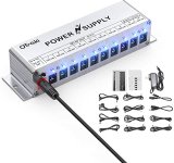
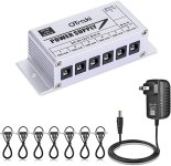
I have a number of these small and compact O’traki power supplies in both sizes:
6851421F-81D6-4894-A194-629381C5DE4E.jpeg

59A87AE1-A4B9-406F-98EA-6EA7324A92A2.jpeg


They won’t win me any style points on TGP but they are pretty quiet and I like their size. Also, since I make my own boards out of wood, I like the mounting flanges.

The one thing that bugs me a bit is the combination of outlets on each. I really love the small one but it doesn’t have an 18 vDC output. I like the big one as well because of the 12 and 18 vDC outlets but it only has one 500 mA 9 vDC outlet.

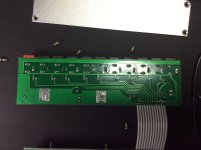
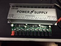
I had a few spares so I cracked one open last night to see what was going on:
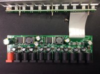
5AA0BDDC-EC58-4AA8-BAEE-140373CF154C.jpeg E75F52B8-3CEF-44E8-8647-5335E66478D8.jpeg D70673BC-5885-4A0D-BD8A-E3E991856A1B.jpeg

I reached out to the Amazon seller I buy them from last night. Basically told a little white lie about outputs on both sizes having failed on me and could I get a schematic.

I’d like to get an idea on what’s going on so I can maybe modify some of the outputs to better reflect what I want. Especially in the smaller size, which I’m using right now on my boards.

Can anyone make heads or tails of some of the components?
 
Pssh, why spend money when you can spend hours of frustration? :p Realistically it should only be a few minutes though.

Can you read the part numbers on those 5-pin ICs? It's hard to read in the pictures with the lighting. Those are going to be the switching regulators for the outputs, and the resistors next to them (looks like 0603 package maybe?) are going to set the voltages. Like @fig says, using the datasheet you should be able to figure out which one is the feedback resistor and you can find the equation for what value to use to adjust the voltage and swap it.
 
Buy an isolated one that has what you actually want. The onespot or voodoo labs will last you years, be quieter (the above is basically a daisy chain) and give you the option to connect two outputs for higher voltage, power consumption and positive ground effects. You get what you pay for and as I alsways say... with quality you buy once cry once.

I'm with you 100%. I'm not looking to these as a permanent solution. I have my eye on the Strymon Ojai or the MXR Iso-Brick because of their small sizes and options.

This is simply an interesting experiment for the short term.
 
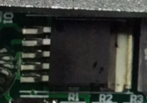
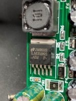
Here are closeup shots of the voltage regulators:

PS1.jpg

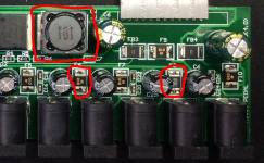
I'm assuming the SMD components circled below are fuses for thier respective taps. Is the black box circled a transformer?:

PS3.png
 
The smaller circled components are ferrite beads, just in-line filters for each tap, which give a degree of isolation aside from their filtering element.

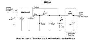
The big black box is a power inductor used for the switch-mode power supply, the LM2956-ADJ. I found the datasheet, I'll take a look and see what resistor values you need to change for the voltage output.
 
...or you could have all of us do this for you :unsure:

Nah! Just needed a point in the right direction. Not used to SMD components so my eyes glazed over a bit. I have the data sheet pulled and was just looking over the calcs for resistor values on the output.

I'll run some checks and see what voltages are coming out of the regulators and into the taps.
 
  • Like
Reactions: fig
Mmkay, I think I got it. So looking at the spot you're zoomed in on, R4, R5, and R6 are the resistors that are setting the voltage. In this case R5 and R6 are in series.

R4 - 1k
R5 - 2k
R6 - 6.8k

In the feedback resistor setup of the datasheet R4 is your "R1" and R5+R6 is your "R2."

So based on the datasheet we see:

Vout = 1.23 ( 1 + R2/R1)

Which in this case means

Vout = 1.23 (1 + 8.8k/1k)
Vout = 1.23 (1 + 8.8)
Vout = 1.23 (9.8)
Vout = 12.054V

So this is the regulator for your 12V tap. Datasheets are neat :cool:
 
Mmkay, I think I got it. So looking at the spot you're zoomed in on, R4, R5, and R6 are the resistors that are setting the voltage. In this case R5 and R6 are in series.

R4 - 1k
R5 - 2k
R6 - 6.8k

So based on the datasheet we see:

Vout = 1.23 ( 1 + R2/R1)

Which in this case means

Vout = 1.23 (1 + 8.8k/1k)
Vout = 1.23 (1 + 8.8)
Vout = 1.23 (9.8)
Vout = 12.054V

So this is the regulator for your 12V tap. Datasheets are neat :cool:

So basically un-modified voltage is being sent to the 12 vDC/100 mA tap. the 8 9 vDC taps must be dropped somehow from 12 vDC. And then the 12 vDC must get stepped up to 18 vDC for that tap.

My other goal would be to increase the current capacity on a few of the 9 vDC taps to accommodate more than one digital effect.

1643209220619.png
 
Oops, left out the idea part...anyway, you could make one port adjustable apparently..

Nice datasheeting @vigilante398 !

Me likey! This would be especially useful on the smaller 7 output unit, as I'd like the 12 vDC tap to be able to drop down to 9 vDC and up to 18 vDC.
 
It's basically an array of DC buck converters...someone smack me if that's wrong.
 
So basically un-modified voltage is being sent to the 12 vDC/100 mA tap. the 8 9 vDC taps must be dropped somehow from 12 vDC. And then the 12 vDC must get stepped up to 18 vDC for that tap.

My other goal would be to increase the current capacity on a few of the 9 vDC taps to accommodate more than one digital effect.
It's more likely that the 18V tap comes straight off the 18V input with a little filtering. I had a couple of these units, the wall wart they use is 18VDC. I would also bet that the 9V regulator also uses the 18V input directly, otherwise all the power would be coming from the 12V regulator and it would get bogged down.

Since the 9V taps are all off the same regulator the only thing really limiting the current output of each tap would be the filter of each one, so as long as you don't exceed the output of the regulator (3A) or the power of the wall wart (1A @ 18V = 18W) you should be able to exceed the stated 100mA output. The ferrite beads may be low rated, but if you jumper those then you're basically turning it into a real daisy chain with no isolation.

I was typing this when you responded! I forgot the input is 18 vDC off the wall wart.

So let me see if I understand things so far:

1.) 18 vDC input is tapped directly with some filtering for the the 18 vDC output tap

2.) There is a dedicated regulator that steps down the 18 vDC to 12 vDC and supplies to the 12 vDC tap.

3.) There is a dedicated regulator that steps down the 18 vDC to 9 vDC and supplies to the 9 vDC taps.

4.) The maximum current output capacity is dictated by the capacity of the regulators

5.) One could technically increase the current capacity of the taps by increasing the maximum capacity of the wall-wart (as long as that does not exceed the maximum of the regulator with an adequate safety margin) and also increase the ratings of the ferrite beads to accommodate.
 
Oh the inductor. So in a SMPS you design for what you want it to do, not what it's capable of doing. The inductor they're using on the SMPS (black box marked 101) looks like the one I use on some of my pedals, which if true is a 100uH 2A inductor. If that's the case then you won't be able to exceed 2A and will likely be limited to around 1.8A because the inductor will saturate and you will have a bad time.

That being said if this regulator was 100% efficient (it's high efficiency, but nothing is 100%) you would still be limited to 2A @ 9V because of your 18W wall wart. If you find a different 18VDC supply to feed the box with you could suck a lot more current out of the ports.

So the current "limits" they print on the box seem to be lies, but there still are limits you need to be aware of.
 
I was typing this when you responded! I forgot the input is 18 vDC off the wall wart.

So let me see if I understand things so far:

1.) 18 vDC input is tapped directly with some filtering for the the 18 vDC output tap

2.) There is a dedicated regulator that steps down the 18 vDC to 12 vDC and supplies to the 12 vDC tap.

3.) There is a dedicated regulator that steps down the 18 vDC to 9 vDC and supplies to the 9 vDC taps.

4.) The maximum current output capacity is dictated by the capacity of the regulators

5.) One could technically increase the current capacity of the taps by increasing the maximum capacity of the wall-wart (as long as that does not exceed the maximum of the regulator with an adequate safety margin) and also increase the ratings of the ferrite beads to accommodate.
Lol and now I was typing when you replied :p Correct on all counts.
 
  • Like
Reactions: fig
I'm waiting for the destruction of smd components and the new amazon order..

I have a bunch of these. I use one as a benchtop supply for testing and a few others are extras right now. I can sacrifice one for experimentation without losing sleep or having to make any late night emergency purchases!
 
Back
Top