Mountain Oyster Ge Boost - Chuck D. Bones Design

MichaelW

Well-known member
So this is the third of the boards from @fig. I was totally not expecting it, but I love boosts! I cannot lie....@fig must know this:)

Anyway, another board courtesy to the Pedal Triumvirate @Chuck D. Bones design, @cooder @ Bignoise Amplification layout and @fig Logistics and Supply Chain!

Super easy build at first glance but if you read Chucks Breadboard post here....you can see that the details of the specs of both the GE NPN and JFET specs needed to the correct voltages for best performance. I wound up using a random 2N5458 as a starting point just to get the pedal built and tested. (more on that in a bit)

The Ge is a GT404B and one of the only 2 NPN's I had in the correct HFE range, So it's staying in, tomorrows project is figure out how to calculate Vp and sort JFETs hahaha. Having said that even with the not quite right FET in there pedal sounds great!
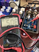
(Ge Collector voltage was 5.98v so it's right in there according to the schematic)

Not really a super clean boost but more like dirtier and dirtier, it actually functions as it's own overdrive.

There's a 3 way toggle, Middle is clean-ish but you can crank the gain for an overdrive sound, top position is 10db volume boost, down toggle position brings in the Ge and turns it into a Treble Booster, very cool! The only pedals I've tried pushing with it last night is the Cattle Driver and CowPoker so far. With the Cattle Driver it sounds amazing! With the Cowpoker it's sick over the top...hahah. But all on its own it can provide some nice crunch even in the middle toggle setting.

For those you sitting on this board, highly reccomend you build it!

The only sub I made was for the 3u3 film cap, the schematic (attached below) shows 1uf in @Chuck D. Bones original circuit so I went with that.

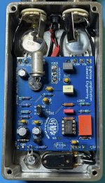
Like in my "lessons learned" from the 'Lectric Mama Flanger and CowPoker boards, there are a few additional components on this board that are not in the schematic.
It's such a low parts count that I did not bother creating a BOM list but pulled parts from the schematic.

Missing from the schematic (if you're building this)
All related to the relay switching circuit:

1k r
10k r
4k7 r
78L05
100p caps x 3
Relay Pic (sent by @fig)
Relay (sent by @fig)

This is another killer @Chuck D. Bones design. Going to play around with testing some JFets to find one with the correct Vp today.

I was chatting with Chuck offline last night and he confirmed my random 2N5458 is "no bueno" for this circuit.
I'm only getting 2.6v at the Drain leg of the FET. It should be ~ 5v with the correct Vp in the FET.

It sounds so dang good with it the way it is, I'm eager to see what it sounds like with the correct value FET in there!!

Thank you again @Chuck D. Bones, @cooder and @fig!!!

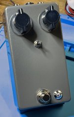
This is my last Tayda Glimmer Brown Sugar enclosure. Trying to hold off ordering any more enclosures until I used up what I have left.

I had to do an "angled leg bend" on the pots in order to get the holes in the right place to use those cool knobs that have been looking for a project.
They're really tall and I thought they might overpower the size of a 125B but I think they turned out ok.

I used a set of the Tayda open frame jacks. These are .87 ea today!! Ridiculously good jack for that kind of price.
Quality I would say falls somewhere near the GLS and Neutrik Rean jacks I had been using but these cost less.

They are slightly shorter in overall length of the "tip leg" so it also saves a little space for tight builds.
One last benefit is that the solder lugs don't reject solder like the GLS jacks do. These are my new goto jacks for sure! Thank you @cdwillis and @Coda for the tip.
Digging these! @Roberman @Route14 you should definitely throw a couple of these on your next Tayda order.
IMG_3741.JPG

IMG_3739.JPG

Edit: forgot to attach the schematic....here it is.....mind the voltages on the FET and Ge. Those are the targets you want.
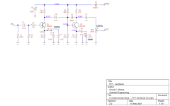
FET-Ge Boost v2.2.png
 
Last edited:
I was just thinking, I can’t believe you haven’t finished this one yet.
Awesome look to this one I love these tayda silver based enclosures and those Neve knobs are a fave as well. I should have mine done this week and thanks for the heads up on the jfet. For sure using sockets on this one.
Another great build man. I really don’t know how you crank out so many. Kudos.
Yah, I have no excuse....except that I actually had to work yesterday.....egads! Busy day full of meetings. The NERVE of those folks, don't they KNOW I have PEDALS TO BUILD????? I didn't get to my bench until after dinnertime.
 
Update: (no not a demo, heh)

Ok, as mentioned in my OP, I had a random 2N5458 JFET in there to just test for operation.

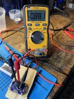
The voltage I was getting at Q1-Drain was only 2.61v which was way off from Chuck's design.
Curiously, the Vp of that FET was in the right range (-1.5-ish)

So I learned a new thing today. That Vp (voltage pinch off) while technically not the same as Vgs off, is effectively the same value disregarding polarity. So armed with this new knowledge that totally expanded my wee little brain, I used my RullyWow Jfet matcher board to find something suitable and close to the -1.4v that Chuck was getting with his 2N5246.

I went through about 20 different JFets of various types (2N5457, J201, MMBFJ201, MMBF5457, J113) and all the ones I had that measured -1.5v Vp were not giving me the right voltage at the drain leg "in circuit". This was confusing and frustrating to me.

So I changed tactics, instead of targeting the Vp on the FET I decided to to target the 5.07v at Q1-Drain "in circuit" in Chuck's schematic.

Even more curiously, what got me there was an MMBF5457 that had a Vp (Vgs-off) of -0.881v.
Which yielded a Q1-Drain voltage of 5.08v WOOHOOO!

Maybe one of you smart people can explain why this is. Is it the difference between the 2N5246 vs MMBF5457?

Anyway, this has all been academic because the pedal SOUNDED great before and SOUNDS great now.
Just listening to it now, the gain might be a bit more saturated and a wee bit smoother, or this might be a placebo effect, not sure.
(Oh and incidentally, my Ge NPN GT404B has 5.98v at Q2-Collector, that's right in there!)

I'm calling this one done and putting the screws in the back cover!

IMG_3756.JPG

IMG_3755.JPG
 
So this is the third of the boards from @fig. I was totally not expecting it, but I love boosts! I cannot lie....@fig must know this:)

Anyway, another board courtesy to the Pedal Triumvirate @Chuck D. Bones design, @cooder @ Bignoise Amplification layout and @fig Logistics and Supply Chain!

Super easy build at first glance but if you read Chucks Breadboard post here....you can see that the details of the specs of both the GE NPN and JFET specs needed to the correct voltages for best performance. I wound up using a random 2N5458 as a starting point just to get the pedal built and tested. (more on that in a bit)

The Ge is a GT404B and one of the only 2 NPN's I had in the correct HFE range, So it's staying in, tomorrows project is figure out how to calculate Vp and sort JFETs hahaha. Having said that even with the not quite right FET in there pedal sounds great!
(Ge Collector voltage was 5.98v so it's right in there according to the schematic)

Not really a super clean boost but more like dirtier and dirtier, it actually functions as it's own overdrive.

There's a 3 way toggle, Middle is clean-ish but you can crank the gain for an overdrive sound, top position is 10db volume boost, down toggle position brings in the Ge and turns it into a Treble Booster, very cool! The only pedals I've tried pushing with it last night is the Cattle Driver and CowPoker so far. With the Cattle Driver it sounds amazing! With the Cowpoker it's sick over the top...hahah. But all on its own it can provide some nice crunch even in the middle toggle setting.

For those you sitting on this board, highly reccomend you build it!

The only sub I made was for the 3u3 film cap, the schematic (attached below) shows 1uf in @Chuck D. Bones original circuit so I went with that.

Like in my "lessons learned" from the 'Lectric Mama Flanger and CowPoker boards, there are a few additional components on this board that are not in the schematic.
It's such a low parts count that I did not bother creating a BOM list but pulled parts from the schematic.

Missing from the schematic (if you're building this)
All related to the relay switching circuit:

1k r
10k r
4k7 r
78L05
100p caps x 3
Relay Pic (sent by @fig)
Relay (sent by @fig)

This is another killer @Chuck D. Bones design. Going to play around with testing some JFets to find one with the correct Vp today.

I was chatting with Chuck offline last night and he confirmed my random 2N5458 is "no bueno" for this circuit.
I'm only getting 2.6v at the Drain leg of the FET. It should be ~ 5v with the correct Vp in the FET.

It sounds so dang good with it the way it is, I'm eager to see what it sounds like with the correct value FET in there!!

Thank you again @Chuck D. Bones, @cooder and @fig!!!

This is my last Tayda Glimmer Brown Sugar enclosure. Trying to hold off ordering any more enclosures until I used up what I have left.

I had to do an "angled leg bend" on the pots in order to get the holes in the right place to use those cool knobs that have been looking for a project.
They're really tall and I thought they might overpower the size of a 125B but I think they turned out ok.

I used a set of the Tayda open frame jacks. These are .87 ea today!! Ridiculously good jack for that kind of price.
Quality I would say falls somewhere near the GLS and Neutrik Rean jacks I had been using but these cost less.

They are slightly shorter in overall length of the "tip leg" so it also saves a little space for tight builds.
One last benefit is that the solder lugs don't reject solder like the GLS jacks do. These are my new goto jacks for sure! Thank you @cdwillis and @Coda for the tip.
Digging these! @Roberman @Route14 you should definitely throw a couple of these on your next Tayda order.

View attachment 34513

View attachment 34514

Edit: forgot to attach the schematic....here it is.....mind the voltages on the FET and Ge. Those are the targets you want.

View attachment 34516
That pedal looks amazing man! Great work and build report as always
 
Thanks for the timely reply! I'll measure it from the pcb then!
I measured my coworker from the knobs on the circuit. So in other words I built the circuit then measured from pot to pot. Came out perfect for me. Just have to do a little extra measuring that’s all!
 
So I learned a new thing today. That Vp (voltage pinch off) while technically not the same as Vgs off, is effectively the same value disregarding polarity. So armed with this new knowledge that totally expanded my wee little brain, I used my RullyWow Jfet matcher board to find something suitable and close to the -1.4v that Chuck was getting with his 2N5246.

I went through about 20 different JFets of various types (2N5457, J201, MMBFJ201, MMBF5457, J113) and all the ones I had that measured -1.5v Vp were not giving me the right voltage at the drain leg "in circuit". This was confusing and frustrating to me.

So I changed tactics, instead of targeting the Vp on the FET I decided to to target the 5.07v at Q1-Drain "in circuit" in Chuck's schematic.

Even more curiously, what got me there was an MMBF5457 that had a Vp (Vgs-off) of -0.881v.
Which yielded a Q1-Drain voltage of 5.08v WOOHOOO!

Maybe one of you smart people can explain why this is. Is it the difference between the 2N5246 vs MMBF5457?
First of all, that build looks amazing!! I'm looking forward to hear it in some of your amazing demos

If I'm not mistaken (and I could very well be, it's late and I had a couple beers), the rullywow jfet matcher does not provide vgs-off values, but rather the voltage value at which the jfet behaves as a 10k resistor (http://www.geofex.com/article_folders/fetmatch/fetmatch.htm), so I'm guessing vgs-off would be higher (more negative). That would explain the difference.

If you have a protoboard, runoffgroove has a very simple circuit that is supposed to give good measurements of Vgs-off and Idss (Fig 10 in this page https://runoffgroove.com/fetzervalve.html). You could measure the fet you have in place to see if vgs-off is closer to -1.5V
Yes you are correct, the RullyWow board actually only measures VGSoff at a certain RDS, (e.g., that 10kr). It's fine for matching JFets for phasers but doesn't really give you absolute Vp. I think Chuck mentioned that one of the 10kr's would need to be like 1meg or something (over my head hahaha).

But for my purposes it helped me hone in on the right circuit voltage.
 
I measured my coworker from the knobs on the circuit. So in other words I built the circuit then measured from pot to pot. Came out perfect for me. Just have to do a little extra measuring that’s all!
When I do the Mockups in Photoshop, I paste the PCB picture flipped horizontal on the Graphic to scale to be designed & match with existing Drill layouts if available & then drop it 16mm down for LED's & Toggle Switches.
l also boost it Double Size for accuracy check!
 
Last edited:
First of all, that build looks amazing!! I'm looking forward to hear it in some of your amazing demos

If I'm not mistaken (and I could very well be, it's late and I had a couple beers), the rullywow jfet matcher does not provide vgs-off values, but rather the voltage value at which the jfet behaves as a 10k resistor (http://www.geofex.com/article_folders/fetmatch/fetmatch.htm), so I'm guessing vgs-off would be higher (more negative). That would explain the difference.

If you have a protoboard, runoffgroove has a very simple circuit that is supposed to give good measurements of Vgs-off and Idss (Fig 10 in this page https://runoffgroove.com/fetzervalve.html). You could measure the fet you have in place to see if vgs-off is closer to -1.5V
I suck at breadboarding, but I've only tried it once and even following @BuddytheReow's most excellent tutorials my simple LPB-1 didn't work and I never went back to figure out why. It's definitely a skill I need to expand into but honestly, my hearts not just in it quite yet.

Having said that, I'm running into more and more situations that learning some simple breadboarding would be immensely helpful. I would love to be able to build some of @Chuck D. Bones's circuits on a giant protoboard. I would also love to learn how to do Vero and be able to do a FULLY DIY pedal. But given I've only been building pedals at all for less than a year I'm not putting any pressure on myself to learn all that stuff.

I DO have everything I need though, I bought one of @Robert's Protoboards, and I think I really need a couple more. I also bought a breadboarding kit off Amazon that's got a bunch of different size boards and all the connectors and stuff.

To be honest, I look at all that stuff and have the same feeling I have every time I try to learn an Eric Johnson tune.....I'm like "Hell yah I can play that part.....but wait....wtf is he doing there? Whoa......nvm......"
 
Nope, sorry, I just winged it.

Neither quite match the PPCB patterns.
Actually, This is not "quite" true, I think I mentioned in my 'Lectric Mama post that from side to side the knob measurements are very close to the PPCB 6 knob template. But the two rows of 3 knobs are spaced about 5mm closer together. I would not trust this for ordering a pre-drilled enclosure from Tayda but it will get you pretty close if you are self drilling.

The Mountain Oyster I let the knobs that I wanted to use inform the drill pattern. These Neve console knobs are pretty big and tend to hang off the edges using the PPCB templates (which drives me nuts). So I knew I had some wiggle room with manipulating the legs of the 2 pots. (Much harder to do with 4 pots). So I laid out how I wanted the knobs first then bent the pot legs to fit that. Working a bit backwards but it worked.
 
I suck at breadboarding, but I've only tried it once and even following @BuddytheReow's most excellent tutorials my simple LPB-1 didn't work and I never went back to figure out why. It's definitely a skill I need to expand into but honestly, my hearts not just in it quite yet.

Having said that, I'm running into more and more situations that learning some simple breadboarding would be immensely helpful. I would love to be able to build some of @Chuck D. Bones's circuits on a giant protoboard. I would also love to learn how to do Vero and be able to do a FULLY DIY pedal. But given I've only been building pedals at all for less than a year I'm not putting any pressure on myself to learn all that stuff.

I DO have everything I need though, I bought one of @Robert's Protoboards, and I think I really need a couple more. I also bought a breadboarding kit off Amazon that's got a bunch of different size boards and all the connectors and stuff.

To be honest, I look at all that stuff and have the same feeling I have every time I try to learn an Eric Johnson tune.....I'm like "Hell yah I can play that part.....but wait....wtf is he doing there? Whoa......nvm......"
You might want to take another stab at breadboarding. Start simple by lighting up a diode (and not burning it out, haha). We, not just myself, would be happy to help you troubleshoot your board if you run into problems. You haven't gotten the drive yet to breadboard simply because you haven't been successful yet. Once you get one circuit to work it will catch on quickly. If you enjoy puzzles/problem solving this is definitely the way to go.

That being said, you might also want to venture out into stripboard territory for a new challenge. Solder is more forgiving on stripboard. A big board from Tayda is dirt cheap and you can get a few builds out of one depending on how complex the circuit is. Perfboard, not stripboard, has an additional challenge being point to point and making bridges everywhere so I would start with stripboard. There are tons of layouts out there including PPCB circuits, but I would start with a simple 1 knob fuzz just so you understand the process. Again, if you need help on this just ask.
 
When I do the Mockups in Photoshop, I paste the PCB picture on the Graphic to scale to be designed & match with existing Drill layouts if available & then drop it 16mm down for LED's & Toggle Switches.
l also boost it Double Size for accuracy check!
This is how I do my enclosures! I used to just take taydas drill template for the sized enclosure then using my sniping tool to cut out the drill template and resize to fit the template I got from tayda and I’m good to go I start designing from there.
 
Back
Top