Coda
Well-known member
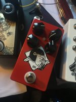
This one showed up today, and was the only thing on hand that I could build without placing a parts order…or so I thought. A bit of background: I first discovered the Os Mutantes circuit last Summer sometime. Fast forward to a few weeks ago, and I was super excited to see the Basic Audio variant available here. I ordered it on Sunday (along with several other pcbs), and it arrived today. I wasn’t sure if I could built it, since there are no build docs, and was happy that, after looking over the PCB, it looked like I had all the parts I needed.
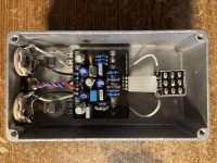
Not many parts in this one. I placed the first component…I think it was a 4k7. Next component to place: 3M3. I grab my 3M3 drawer and pull out a component. I stopped…the bands didn’t look right. Popped it in my tester: they are 3k3, not 3M3. Ootz. Looking a bit closer, there were a few components I was short on. No BC549B (I do have C, however). I settled on 2n5088. Oh well. A few sockets later I was ready for substitutions. The 3M3 became two 1M5 resistors in series. 4n7 caps because 3n9s that measured almost 4n2. I socketed the diodes too cause hey, why not?
I started this at 2pm this afternoon. At 4pm I plugged it in. It was a bit strange. Sounded kinda weird. I decided to replace the 5088’s with whatever else I had on hand that came close to BC549B. Settled on a trio of 2n2222 that all measured in the mid-200’s.
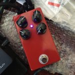
This is a really cool circuit. It definitely is a vintage 1960’s feel, but with way more versatility than most 60’s fuzzes. You can dial in OD/Distortion tones, raw splatty fuzz, or buzzy goodness. I was pretty impressed, and I didn’t even really get to know it yet.
Anywho, here’s a gutshot and a rough demo vid. No artwork yet because I’m working on that…
Not many parts in this one. I placed the first component…I think it was a 4k7. Next component to place: 3M3. I grab my 3M3 drawer and pull out a component. I stopped…the bands didn’t look right. Popped it in my tester: they are 3k3, not 3M3. Ootz. Looking a bit closer, there were a few components I was short on. No BC549B (I do have C, however). I settled on 2n5088. Oh well. A few sockets later I was ready for substitutions. The 3M3 became two 1M5 resistors in series. 4n7 caps because 3n9s that measured almost 4n2. I socketed the diodes too cause hey, why not?
I started this at 2pm this afternoon. At 4pm I plugged it in. It was a bit strange. Sounded kinda weird. I decided to replace the 5088’s with whatever else I had on hand that came close to BC549B. Settled on a trio of 2n2222 that all measured in the mid-200’s.
This is a really cool circuit. It definitely is a vintage 1960’s feel, but with way more versatility than most 60’s fuzzes. You can dial in OD/Distortion tones, raw splatty fuzz, or buzzy goodness. I was pretty impressed, and I didn’t even really get to know it yet.
Anywho, here’s a gutshot and a rough demo vid. No artwork yet because I’m working on that…
Attachments
Last edited: